HelpDesk
How to Create an IDEF0 Diagram for an Application Development
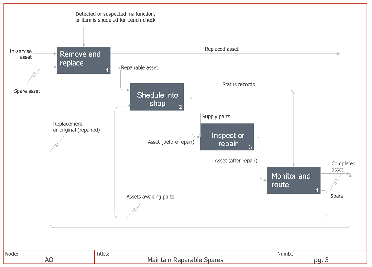
IDEF0 methods are intended to model the functions of a process, creating a graphical model that displays: what controls the function, who makes it, what resources are used and how they are connected with other functions. The IDEF0 tool is used to model the decisions, actions, and activities of a software system during the development process. IDEF0 diagram graphically depicts a model of a desired version of the application. ConceptDraw DIAGRAM allows you to create and communicate the IDEF0 diagrams of any complexity.Software development with ConceptDraw products
Internet solutions on ConceptDraw base. What may interest developers of Internet solutions.Software development with ConceptDraw DIAGRAM
Modern software development requires creation of large amount of graphic documentation, these are the diagrams describing the work of applications in various notations and cuts, also GUI design and documentation on project management. ConceptDraw DIAGRAM technical and business graphics application possesses powerful tools for software development and designing technical documentation for object-oriented projects. Solutions included to the Software Development area of ConceptDraw Solution Park provide the specialists with possibility easily and quickly create graphic documentation. They deliver effective help in drawing thanks to the included package of templates, samples, examples, and libraries with numerous ready-to-use vector objects that allow easily design class hierarchies, object hierarchies, visual object-oriented designs, flowcharts, GUI designs, database designs, visualize the data with use of the most popular notations, including the UML and Booch notations, easy manage the development projects, automate projection and development.Use Case Diagrams technology with ConceptDraw DIAGRAM
Use case diagrams are used at the development of software and systems for definition of functional system requirements or system of systems. Use case diagram presents the consecution of object’s actions (user’s or system’s) which are executed for reaching the definite result.HelpDesk
How to Create and Customize a Calendar
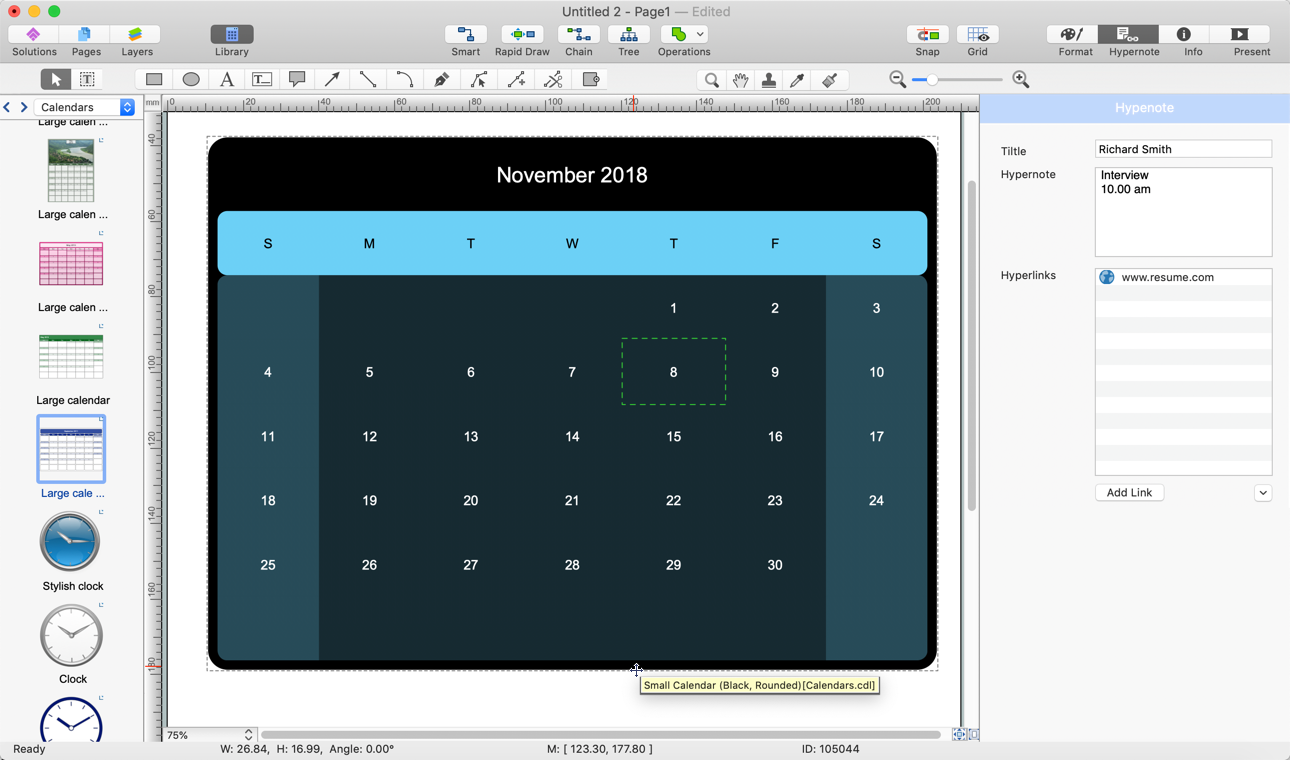
ConceptDraw DIAGRAM has a large selection of various shapes, objects, and clip-arts. It also has a tool that helps you find exactly what you need. ConceptDraw DIAGRAM has calendar objects available, and it's very easy to customize it and set your dates. The ability to create a custom calendars is delivered by the Calendars solution. With the help of ConceptDraw DIAGRAM, you can create a calendar that helps you plan your day/ week/month and do not forget about the important things in life. For any day in your custom calendar, you can create a task list and add hyperlinks to a relevant information.
 Event-driven Process Chain Diagrams
Event-Driven Process Chain Diagrams solution extends ConceptDraw DIAGRAM functionality with event driven process chain templates, samples of EPC engineering and modeling the business processes, and a vector shape library for drawing the EPC diagrams and EPC flowcharts of any complexity. It is one of EPC IT solutions that assist the marketing experts, business specialists, engineers, educators and researchers in resources planning and improving the business processes using the EPC flowchart or EPC diagram. Use the EPC solutions tools to construct the chain of events and functions, to illustrate the structure of a business process control flow, to describe people and tasks for execution the business processes, to identify the inefficient businesses processes and measures required to make them efficient.
- Software Development Flow Diagram
- Venn diagram - Path to sustainable development | Process ...
- Software Development Process Flow Diagram
- Software Work Flow Process in Project Management with Diagram ...
- Functional Modeling Of Software Process Using Idef0
- System Organisation Design Using Dfd
- Swim Lane Diagrams | Cross-Functional Flowchart (Swim Lanes ...
- Structured Systems Analysis and Design Method (SSADM) with ...
- Gantt Chart For Software Development Sample
- Flowchart For Software Development Process
- Business Development Process Flowchart
- Software development with ConceptDraw Products | Software ...
- Process Flowchart | Sales Process Flowchart. Flowchart Examples ...
- Gantt Chart For Software Development Process
- Process Flowchart | Software development with ConceptDraw PRO ...
- Software Work Flow Process in Project Management with Diagram ...
- Flowchart Of A Software Development Procedure
- Process Flowchart | Basic Flowchart Symbols and Meaning | Sales ...
- Process Flowchart | Software and Database Design with ...
- Creating Flow Chart For The Solution To A Software Development


