HelpDesk
ConceptDraw Software Full Versions Free Download
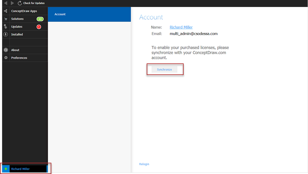
ConceptDraw software provides registered users a 21 day trial period at no charge. It functions exactly as a fully licensed copy of the product does. Once you have activated your account you are then able to download and install ConceptDraw software as well, as solutions from Solution Park. Here is an instructions on how to download and try ConceptDraw products for free. For 21 days the trial functions exactly like the purchased product. There are no limitations to file size, how many times you can print, or any of the products functionality. After the trial period expires, you will be able to open ConceptDraw documents to view.HelpDesk
How to Convert ConceptDraw DIAGRAM v12 file into MS Visio 2003-2010 format
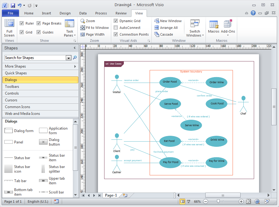
Many people use the MS Visio as a business graphic creation program. It is a powerful application with advanced ability to support complex solutions. The native file format for Visio 2010 and earlier files is VSD. ConceptDraw DIAGRAM supports export to Visio XML files (VDX). The transfer process is very simple. You can easily share your ConceptDraw Documents with MS Visio 2007/2010 users. changing software products, you can keep all your documents, created in MS Visio. Using ConceptDraw DIAGRAM , the same as using MS Visio , you will have an opportunity to work with powerful content, provided by Solution Park. You can create various documents with no need to look for the necessary elements for your diagrams in other software products.HelpDesk
How to Convert a Mind Map into MS Word Document
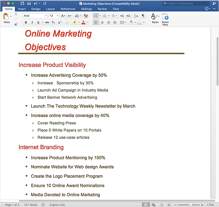
Mind maps are often used for structuring ideas, planning, and organizing of various documents. ConceptDraw MINDMAP allows you to transfer a mind map to MS Word format using its export facilities. You can convert a mind map to an MS Word outline using the set of standard templates, or even your custom template. Thus, your mind map will be transformed into the proper document format. Using a custom MS Word template allows you to apply your individual style to each document, being exported from ConceptDraw MINDMAP. You can use a mind mapping to capture ideas and structure information. Then make a quick conversion to MS Word and you finally obtain a clean and stylish document.- Pert Cpm Software Gratis
- Flow Chart Free Download Gratis
- Flowchart Software Gratis
- Software Uml Gratis
- Cross-Functional Flowchart | How To Create Restaurant Floor Plan ...
- Visio Gratis
- Conceptdraw Mac Gratis
- Steps of Accounting Cycle | Program to Make Flow Chart | Draw ...
- ConceptDraw Software Full Versions Free Download | Flowchart ...
- Best Value Stream Mapping mac Software | Lean Manufacturing ...
- Kanban Software Gratis
- Flowchart Software | Organization Chart Software | Process ...
- Data Flow Diagram Software
- Process Flow Diagram Symbols | Chemical and Process ...
- Building Drawing Software for Designing Plumbing | Interior Design ...
- Process Flowchart | How to Add a Workflow Diagram to a ...
- Porter's Value Chain | Competitor Analysis | Software for Creating ...
- Gym Layout Design Software Free Download
- How To Create Restaurant Floor Plan in Minutes | How To use ...


