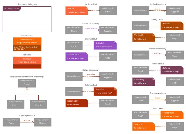
The vector stencils library "Requirement diagram" contains 21 SysML symbols.
Use it to design your requirement diagrams using ConceptDraw PRO diagramming and vector drawing software.
"A requirement specifies a capability or condition that must (or should) be satisfied. A requirement may specify a function that a system must perform or a performance condition a system must achieve. SysML provides modeling constructs to represent text-based requirements and relate them to other modeling elements. The requirements diagram described in this clause can depict the requirements in graphical, tabular, or tree structure format. A requirement can also appear on other diagrams to show its relationship to other modeling elements. The requirements modeling constructs are intended to provide a bridge between traditional requirements management tools and the other SysML models.
A requirement is defined as a stereotype of UML Class subject to a set of constraints. A standard requirement includes properties to specify its unique identifier and text requirement. Additional properties such as verification status, can be specified by the user.
Several requirements relationships are specified that enable the modeler to relate requirements to other requirements as well as to other model elements. These include relationships for defining a requirements hierarchy, deriving requirements, satisfying requirements, verifying requirements, and refining requirements." [www.omg.org/ spec/ SysML/ 1.3/ PDF]
The SysML shapes example "Design elements - Requirement diagram" is included in the SysML solution from the Software Development area of ConceptDraw Solution Park.
Use Case Diagrams technology with ConceptDraw PRO
Use case diagrams are used at the development of software and systems for definition of functional system requirements or system of systems. Use case diagram presents the consecution of object’s actions (user’s or system’s) which are executed for reaching the definite result.- Fishbone Diagram In Software Requirements Engineering
- Flowchart Of Requirements Workflow In Software Engineering
- Building Drawing Software for Design Office Layout Plan | Campus ...
- Cafe Decor | Office Floor Plans | Restaurant Floor Plan Software ...
- Restaurant Floor Plans Samples | Home Design Software | Cooking ...
- Cafe Decor | Restaurant Floor Plan Software | Office Floor Plans ...
- Building Drawing Software for Design Office Layout Plan | Hotel ...
- Fishbone Software Requirements
- Software To Draw Requirements Engineering
- Hotel Management Software Requirements
- Gather Requirements Exchanging Mind Maps with Evernote ...
- Requirements For Seating And Serving Area In A Coffee Shop
- Requirements Of Seating Serving Area For A Small Coffee Shop
- Building Drawing Software for Design Office Layout Plan | Office ...
- Requirements And Layouts Of The Seating And Serving Area Aswell
- Kitchen Planning Software | How To Create Restaurant Floor Plan in ...
- Requirements Of The Seating N Serving Area As Well As The
- Building Drawing Software for Design Site Plan | Site Plans | Cafe ...
- What Are The Requirements And Layouts Of A Small Coffee Shop

