 SWOT and TOWS Matrix Diagrams
SWOT and TOWS Matrix Diagrams solution extends ConceptDraw PRO and ConceptDraw MINDMAP software with features, templates, samples and libraries of vector stencils for drawing SWOT and TOWS analysis matrices and mind maps.
 Sales Flowcharts
The Sales Flowcharts solution lets you create and display sales process maps, sales process workflows, sales steps, the sales process, and anything else involving sales process management.
 Logistic Dashboard
The powerful tools of Logistic Dashboard solution and specially developed live graphic objects of logistic icons, logistic navigation elements, logistic indicators, logistic charts and logistic maps effectively assist in designing Logistic dashboards, Logistic maps, Logistic charts, diagrams and infographics. The included set of prebuilt samples and quick-start templates, demonstrates the power of ConceptDraw PRO software in logistics management, its assisting abilities in development, realization and analyzing the logistic processes, as well as in perfection the methods of logistics management.
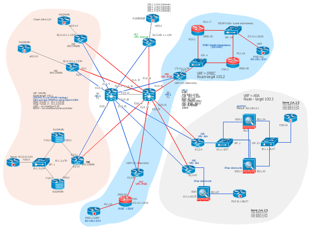
This Cisco network diagram example was drawn on the base of the figure illustrating the post "Cisco Lab 1 : Network Design from the requirement" from the blog "Thai Cisco Club".
"1. Core service porvider by assign P router as P1 and P2, PE router as PE1 - 8 for support CE router of customers.
2. From 1st customer project, assign R1-DMVPN and R2-DWVPN as DMVPN Hub, and R3-DMVPN and R4-DMVPN as DMVPN-Spoke that on different site.
3. From 2nd customer project, assign IP-SEC R1 and IP-SEC R2 as SSO-IP-SEC Router on HQ site, and IP-SEC R3 as branch site that far away."
[thai-cisco-club.blogspot.com/ 2011/ 10/ cisco-lab-1-network-design-from.html]
The diagram example "Cisco network design from the requirement" was created using the ConceptDraw PRO diagramming and vector drawing software extended with the Cisco Network Diagrams solution from the Computer and Networks area of ConceptDraw Solution Park.
- Symboles Organigramme | Draw Fishbone Diagram on MAC ...
- How to Create a Fishbone (Ishikawa) Diagram Quickly | Cause and ...
- Value Stream Mapping | Draw Fishbone Diagram on MAC Software ...
- Root cause analysis tree diagram - Template | Fault Tree Diagram ...
- Vector Graphics Electrical Symbols Ce
- PROBLEM ANALYSIS. Prioritization Matrix | Cause and Effect ...
- How to Create a Fault Tree Analysis Diagram (FTD) in ConceptDraw ...
- Cisco network design from the requirement
- Cisco Network Templates | Cisco network design from the ...
- Cisco network design from the requirement | Dmvpn Network Diagram
