 Entity-Relationship Diagram (ERD)
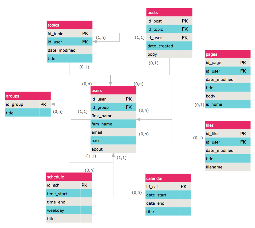
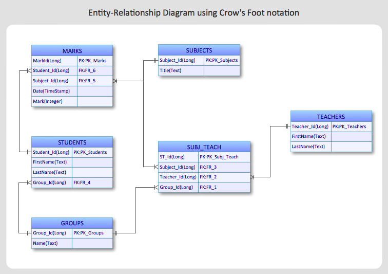
An Entity-Relationship Diagram (ERD) is a visual presentation of entities and relationships. That type of diagrams is often used in the semi-structured or unstructured data in databases and information systems. At first glance ERD is similar to a flowch
 Entity-Relationship Diagram (ERD)
Entity-Relationship Diagram (ERD) solution extends ConceptDraw PRO software with templates, samples and libraries of vector stencils from drawing the ER-diagrams by Chen's and crow’s foot notations.
HelpDesk
How to Create an ERD Diagram
ERD (entity relationship diagram) is used to show the logical structure of databases. It represents the interrelationships between components of database (entities). Entity relationship diagrams are a widely used in software engineering. Using ERD software engineers can control the every aspect of database development. ER diagram can be used as guide for testing and communicating before the release of software product. ERD displays data as entities that are connected with connections that show the relationships between entities. There is some ERD notations used by data bases developers for representing the relationships between the data objects. ConceptDraw PRO and its ERD solution allow you to build ERD diagram of any notation.HelpDesk
How to Create an Entity-Relationship Diagram Using ConceptDraw Solution Park
An entity-relationship diagram (ERD)is used in a database modeling process. ERD diagram shows a graphical representation of objects or concepts within an information system and their relationships.The ability to describe a database using the Entity-Relationship model is delivered by the ConceptDraw ERD solution.
 ConceptDraw Solution Park
ConceptDraw Solution Park collects graphic extensions, examples and learning materials
 Software Development Area
Solutions from the Software Development Area of ConceptDraw Solution Park collect templates, samples and libraries of vector stencils for drawing the software engineering diagrams and user interface design prototypes.
Draw Diagram on Mac
Professional diagramming software for mac helps you create Cause and Effect diagram known as Fishbone diagram or Ishikawa diagram from ConceptDraw Business Solution. You will be offered to use templates, samples or draw your diagram using ConceptDraw Arrows10 Technology- Database Schema For Sport Management System
- Erd Diagram For Sports Management
- Er Diagram For Sports Management Full Hd
- Entity-Relationship Diagram ( ERD ) | Football | Winter Sports | Draw ...
- Entity-Relationship Diagram ( ERD ) | ConceptDraw Solution Park ...
- Entity-Relationship Diagram ( ERD ) | Football | AWS Architecture ...
- Event-driven Process Chain Diagrams | Entity-Relationship Diagram ...
- Sport Field Plans | Entity-Relationship Diagram ( ERD ) with ...
- Er Diagram Solutions Regarding Sports
- Event-driven Process Chain Diagrams | Entity-Relationship Diagram ...
- PM Personal Time Management | Ice Hockey | Football | Sport Shop ...
- Hd Images Of Er Diagram Of Sports Management System
- Entity-Relationship Diagram ( ERD ) | School and Training Plans ...
- Entity-Relationship Diagram ( ERD ) | Chemistry | Cafe Design Ideas ...
- Football Database Er Diagram
- Sport Information System Er Diagram
- Entity-Relationship Diagram ( ERD ) with ConceptDraw PRO | What's ...
- Sports Management System Er Diagram
- Entity-Relationship Diagram ( ERD ) | Soccer | Ice Hockey | Sequence ...
- Entity-Relationship Diagram ( ERD ) | Basketball | Bubble Diagrams ...


