ConceptDraw PRO Database Modeling Software
ConceptDraw PRO is a very easy-to-use and intuitive database design tool which can save you hundreds of work hours. See database diagram samples created with ConceptDraw PRO database modeling database diagram software.ConceptDraw PRO DFD Software
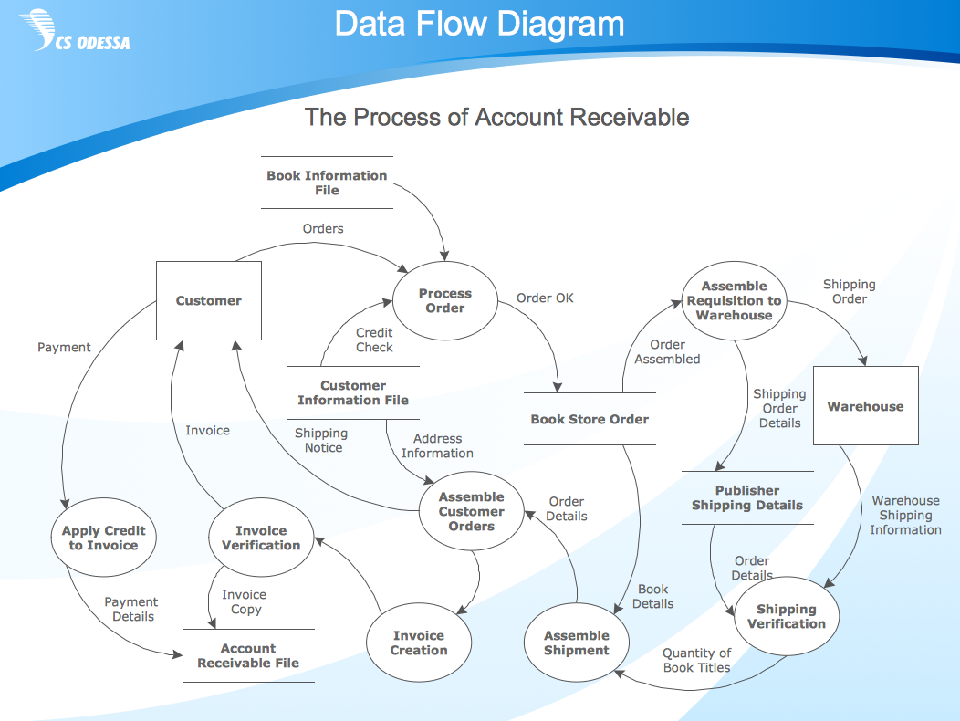
Our DFD software ConceptDraw PRO allows you to quickly create DFD with data storages, external entities, functional transforms, data flows, as well as control transforms and signals. DFD program ConceptDraw PRO has hundreds of templates, and a wide range of libraries with all nesassary ready-made drag-and-drop."In software engineering, an entity–relationship model (ER model) is a data model for describing a database in an abstract way. ...
Crow's Foot notation is used in Barker's Notation, SSADM and Information Engineering. Crow's Foot diagrams represent entities as boxes, and relationships as lines between the boxes. Different shapes at the ends of these lines represent the cardinality of the relationship." [Entity–relationship model. Wikipedia]
This ERD example was redesigned using the ConceptDraw PRO diagramming and vector drawing software from the educational data base model. [www2.cs.uregina.ca/ ~bernatja/ crowsfoot.html]
The example "Entity-relationship diagram (Crow's foot notation)" is included in the Entity-Relationship Diagram (ERD) solution from the Software Development area of ConceptDraw Solution Park.
Use Case Diagrams technology with ConceptDraw PRO
Use case diagrams are used at the development of software and systems for definition of functional system requirements or system of systems. Use case diagram presents the consecution of object’s actions (user’s or system’s) which are executed for reaching the definite result.- Structured Systems Analysis and Design Method ( SSADM ) with ...
- Structured Systems Analysis and Design Method ( SSADM ) with ...
- Data Flow Diagram (DFD) | Structured Systems Analysis and Design ...
- ORM Diagram | Software Diagram Examples and Templates ...
- Create Block Diagram | Block Diagrams | SSADM Diagram | System ...
- SSADM Diagram | Draw Flowcharts with ConceptDraw | Yourdon ...
- GUI Prototyping with ConceptDraw PRO | Software Diagrams ...
- SSADM Diagram | Ssadm Waterfall
- Basic Diagramming | Collaboration in a Project Team | SSADM ...
- Booch OOD Diagram | IDEF0 Diagram | SSADM Diagram | Booch ...
- Stages Of A Ssadm Model In System Development Diagram
- Basic Diagramming | SSADM Diagram | Marketing Diagrams | Block ...
- Data Flow Diagram Ppt For Event Management System
- SSADM Diagram | How to Create a Data Flow Diagram in ...
- Data Flow Diagram | Structured Systems Analysis and Design ...
- Data Flow Diagram | SSADM Diagram | How to Create a Data Flow ...
- Basic Diagramming | SSADM Diagram | Yourdon and Coad ...
- SSADM Diagram | Dfd Waterfall Context Diagram
- Entity Relationship Diagram Symbols and Meaning ERD Symbols ...
- SSADM Diagram | Flowcharts | Process Flowchart | Softwarw ...


.png--diagram-flowchart-example.png)
