 Entity-Relationship Diagram (ERD)
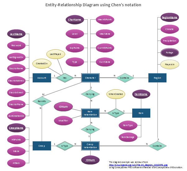
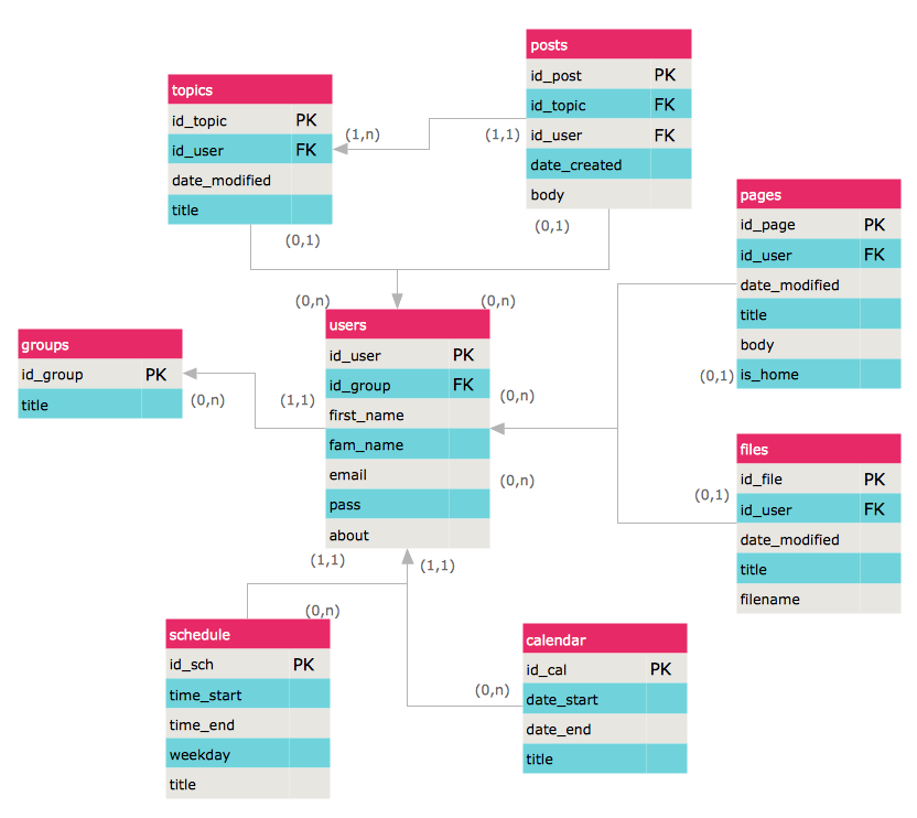
Entity-Relationship Diagram (ERD) solution extends ConceptDraw PRO software with templates, samples and libraries of vector stencils from drawing the ER-diagrams by Chen's and crow’s foot notations.
Data modeling with ConceptDraw PRO
Data modelling will help you to study and analyze business processes in your organization for optimization and increase of effectiveness and production.Data structure diagram with ConceptDraw PRO
Data structure diagram (DSD) is intended for description of conceptual models of data (concepts and connections between them) in the graphic format for more obviousness. Data structure diagram includes entities description, connections between them and obligatory conditions and requirements which connect them. Create Data structure diagram with ConceptDraw PRO.HelpDesk
How to Create an ERD Diagram
ERD (entity relationship diagram) is used to show the logical structure of databases. It represents the interrelationships between components of database (entities). Entity relationship diagrams are a widely used in software engineering. Using ERD software engineers can control the every aspect of database development. ER diagram can be used as guide for testing and communicating before the release of software product. ERD displays data as entities that are connected with connections that show the relationships between entities. There is some ERD notations used by data bases developers for representing the relationships between the data objects. ConceptDraw PRO and its ERD solution allow you to build ERD diagram of any notation.Design Element: Active Directory for Network Diagrams
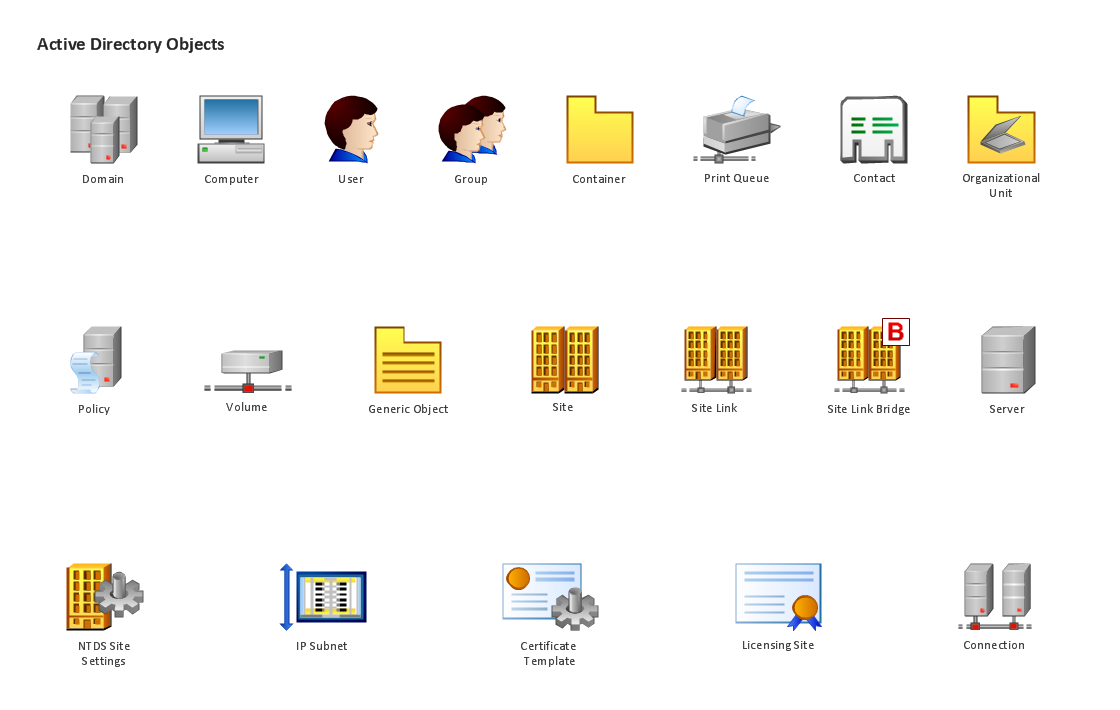
ConceptDraw PRO is perfect for software designers and software developers who need to draw Active Directory Network Diagrams.
- Entity Relationship Diagram Software for Design Crows Foot ER ...
- Components of ER Diagram | Entity Relationship Diagram Symbols ...
- Design elements - ER diagram (Chen notation) | Entity Relationship ...
- Entity-Relationship Diagram (ERD) with ConceptDraw PRO ...
- ER Diagrams with ConceptDraw PRO | IDEF0 standard with
- Entity Relationship Diagram Data Model
- Entity-Relationship Diagram (ERD) with ConceptDraw PRO | IDEF0 ...
- Entity Relationship Diagram Symbols and Meaning ERD Symbols ...
- Process Flowchart | Entity-Relationship Diagram (ERD) with ...
- Entity-Relationship Diagram (ERD) with ConceptDraw PRO | Basic ...
- IDEF0 standard with ConceptDraw PRO | Entity-Relationship ...
- Entity-Relationship Diagram (ERD) with ConceptDraw PRO ...
- Data Flow Diagrams | Entity Relationship Diagram Examples | Entity ...
- Entity-Relationship Diagram (ERD) | ConceptDraw PRO ER ...
- Er Diagram For Event Management
- Graphics Program Draw ER Diagram Symbol By Using Standard
- Entity Relationship Diagram Symbols
- Entity-Relationship Diagram
- Entity-Relationship Diagram (ERD) with ConceptDraw PRO ...
- Entity-Relationship Diagram (ERD) with ConceptDraw PRO | Entity ...


