Data structure diagram with ConceptDraw PRO
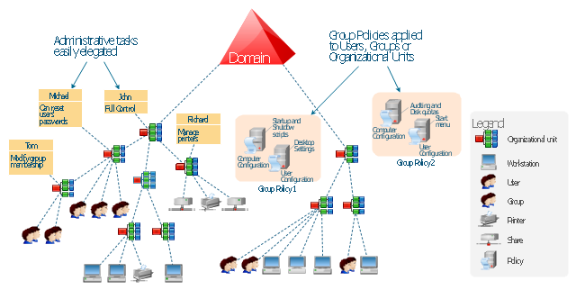
Data structure diagram (DSD) is intended for description of conceptual models of data (concepts and connections between them) in the graphic format for more obviousness. Data structure diagram includes entities description, connections between them and obligatory conditions and requirements which connect them. Create Data structure diagram with ConceptDraw PRO.This example was drawn on the base of the Figure 2 illustrating the "Active Directory FAQ" from the website "Information Management Systems & Services" (IMSS) of the California Institute of Technology (Caltech) campus. [imss.caltech.edu/ node/ 412]
"By using the Active Directory® Domain Services (AD DS) server role, you can create a scalable, secure, and manageable infrastructure for user and resource management, and you can provide support for directory-enabled applications, such as Microsoft® Exchange Server. ...
AD DS provides a distributed database that stores and manages information about network resources and application-specific data from directory-enabled applications. Administrators can use AD DS to organize elements of a network, such as users, computers, and other devices, into a hierarchical containment structure. The hierarchical containment structure includes the Active Directory forest, domains in the forest, and organizational units (OUs) in each domain. A server that is running AD DS is called a domain controller." [technet.microsoft.com/ en-us/ library/ 9a5cba91-7153-4265-adda-c70df2321982]
The Active Directory Domain Services diagram example was created using the ConceptDraw PRO diagramming and vector drawing software extended with the Active Directory Diagrams solution from the Computer and Networks area of ConceptDraw Solution Park.
Control and Information Architecture Diagrams (CIAD) with ConceptDraw PRO
One of the three main constituents of any enterprise is the Control and Information Architecture. The rest two are Production facilities and People and Organization.Use Case Diagrams technology with ConceptDraw PRO
Use case diagrams are used at the development of software and systems for definition of functional system requirements or system of systems. Use case diagram presents the consecution of object’s actions (user’s or system’s) which are executed for reaching the definite result.- Diagram For Water Park Management System Project In Dbms
- Active Directory Diagram | Active Directory Domain Services ...
- Organizational Structure | Active Directory Domain Services diagram ...
- Hierarchical Structure Of Database Management Information System
- Active Directory Structure
- Data Flow Diagram Of Student Database
- Active Directory Diagram | Active Directory structure diagram | Active ...
- Draw Component Diagram For Library Management System And
- Active Directory Structure Diagram Example
- Active Directory structure diagram
- Organizational Structure | Pyramid Diagram | Active Directory ...
- Distributed It
- Domain Structure Diagram
- A Diagrammatic Structure Of Ds
- Active Directory Domain Services diagram | Active Directory ...
- 4 Level pyramid model diagram - Information systems types ...
- Active Directory Domain Services diagram | Active Directory ...
- Active Directory Diagram | Active Directory Domain Services | Active ...
- Active Directory Diagram


