 Plumbing and Piping Plans
Plumbing and Piping Plans solution extends ConceptDraw PRO v10.2.2 software with samples, templates and libraries of pipes, plumbing, and valves design elements for developing of water and plumbing systems, and for drawing Plumbing plan, Piping plan, PVC Pipe plan, PVC Pipe furniture plan, Plumbing layout plan, Plumbing floor plan, Half pipe plans, Pipe bender plans.
 Business Process Mapping
The Business Process Mapping solution for ConceptDraw PRO is for users involved in process mapping and creating SIPOC diagrams.
 Area Charts
Area Charts are used to display the cumulative totals over time using numbers or percentages; or to show trends over time among related attributes. The Area Chart is effective when comparing two or more quantities. Each series of data is typically represented with a different color, the use of color transparency in an object’s transparency shows overlapped areas and smaller areas hidden behind larger areas.
 Entity-Relationship Diagram (ERD)
Entity-Relationship Diagram (ERD) solution extends ConceptDraw PRO software with templates, samples and libraries of vector stencils from drawing the ER-diagrams by Chen's and crow’s foot notations.
 Office Layout Plans
Office layouts and office plans are a special category of building plans and are often an obligatory requirement for precise and correct construction, design and exploitation office premises and business buildings. Designers and architects strive to make office plans and office floor plans simple and accurate, but at the same time unique, elegant, creative, and even extraordinary to easily increase the effectiveness of the work while attracting a large number of clients.
 Electrical Engineering
This solution extends ConceptDraw PRO v.9.5 (or later) with electrical engineering samples, electrical schematic symbols, electrical diagram symbols, templates and libraries of design elements, to help you design electrical schematics, digital and analog
 Education Mind Maps
This solution extends ConceptDraw MINDMAP software with scientific and educational mind maps for educational documents, presentations, and websites.
HelpDesk
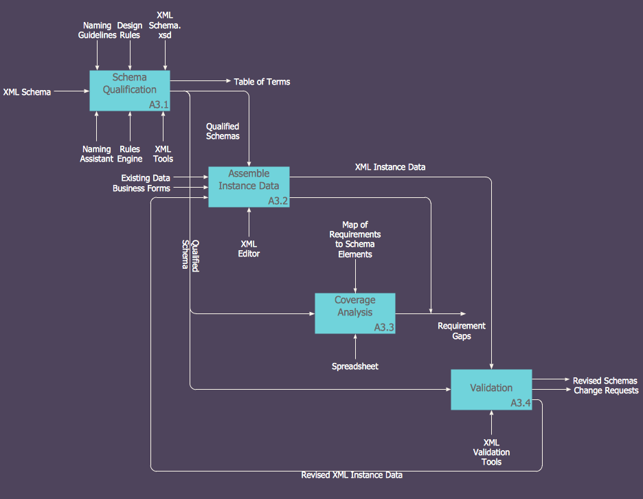
How to Create an IDEF0 Diagram for an Application Development
IDEF0 methods are intended to model the functions of a process, creating a graphical model that displays: what controls the function, who makes it, what resources are used and how they are connected with other functions. The IDEF0 tool is used to model the decisions, actions, and activities of a software system during the development process . IDEF0 diagram graphically depicts a model of a desired version of the application. ConceptDraw PRO allows you to create and communicate the IDEF0 diagrams of any complexity.- Process Flowchart | Total Quality Management Definition | Work ...
- Process Flowchart | Types of Flowcharts | Total Quality Management ...
- Total Quality Management Definition | Value stream map - Template ...
- Event-driven Process Chain Diagrams | Basic Flowchart Symbols ...
- Chain Management System
- Supply Flow Chart
- Supply Chain Process Management
- How To Represent Production Chain Using System Flowchart
- Process Flowchart | Flow chart Example. Warehouse Flowchart ...
- Mac Tools - SWOT Analysis | Process Flowchart | Value Stream ...
- Flow Chart Symbols | ERD Symbols and Meanings | Design ...
- Quality Management Supply Chain
- Process Flowchart | Basic Flowchart Symbols and Meaning | Flow ...
- Process Flow Chart Management
- Flow Chart Symbols | ERD Symbols and Meanings | Business ...
- Lean Quality Management Planning Template
- Procurement process mapping | Work Order Process Flowchart ...
- Process Flowchart | Engineering | Identifying Quality Management ...
- Manufacturing and Maintenance | How Do Fishbone Diagrams ...
- Quality Supply Chain
