HelpDesk
ConceptDraw Office for Windows Installation Definition
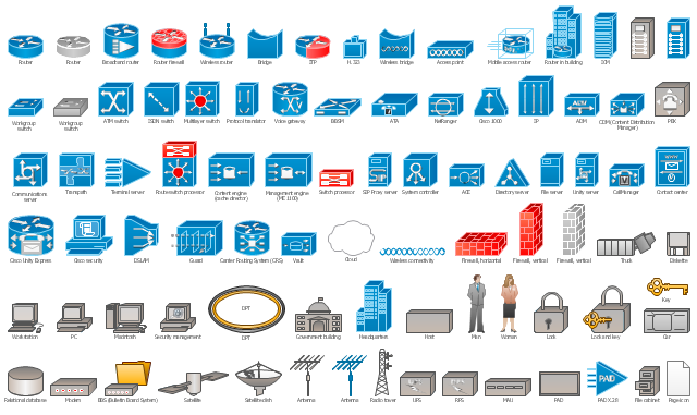
With the introduction of version 3, ConceptDraw Office has been redesigned to better accommodate future developments and solution plugins. ConceptDraw Office 3 includes ConceptDraw PRO 10, ConceptDraw MINDMAP 8, and ConceptDraw PROJECT 7. Owners of ConceptDraw Office v1 and ConceptDraw Office v2, please read this description of the specific features of the ConceptDraw Office 3 installation for Windows before updating.The vector stencils library "Cisco network topology" contains 89 symbols of Cisco network devices and design elements for drawing computer network topology diagrams using the ConceptDraw PRO diagramming and vector drawing software.
"Network topology is an arrangement of the various elements (links, nodes, etc.) of a computer network. Essentially, it is the topological structure of a network, and may be depicted physically or logically. Physical topology refers to the placement of the network's various components, including device location and cable installation, while logical topology shows how data flows within a network, regardless of its physical design. Distances between nodes, physical interconnections, transmission rates, and/ or signal types may differ between two networks, yet their topologies may be identical.
A good example is a local area network (LAN): Any given node in the LAN has one or more physical links to other devices in the network; graphically mapping these links results in a geometric shape that can be used to describe the physical topology of the network. Conversely, mapping the data flow between the components determines the logical topology of the network." [Network topology. Wikipedia]
The example "Design elements - Cisco network topology" is included in the Cisco Network Diagrams solution from the Computer and Networks area of ConceptDraw Solution Park.
HelpDesk
ConceptDraw Office for Apple macOS Installation Definition
With the introduction of version 3, ConceptDraw Office has been redesigned to better accommodate future developments and solution plugins. ConceptDraw Office 3 includes ConceptDraw PRO 10, ConceptDraw MINDMAP 8, and ConceptDraw PROJECT 7. The renewed ConceptDraw STORE helps user manage downloads of ConceptDraw products and solutions. The following article provides owners of the previous versions of ConceptDraw products with important information on updating on ConceptDraw Office v3.HelpDesk
How to Use ConceptDraw Single User License
With ConceptDraw products it is possible to reassign a licensesThe vector stencils library "Network layout floorplan" contain 34 symbol icons for drawing computer network floor plans, communication equipment layouts, and structured cabling diagrams.
"Structured cabling is building or campus telecommunications cabling infrastructure that consists of a number of standardized smaller elements (hence structured) called subsystems. ...
Structured cabling design and installation is governed by a set of standards that specify wiring data centers, offices, and apartment buildings for data or voice communications using various kinds of cable, most commonly category 5e (CAT-5e), category 6 (CAT-6), and fibre optic cabling and modular connectors. These standards define how to lay the cabling in various topologies in order to meet the needs of the customer, typically using a central patch panel (which is normally 19 inch rack-mounted), from where each modular connection can be used as needed. Each outlet is then patched into a network switch (normally also rack-mounted) for network use or into an IP or PBX (private branch exchange) telephone system patch panel." [Structured cabling. Wikipedia]
The design elements example "Network layout floorplan - Vector stencils library" was created using the ConceptDraw PRO diagramming and vector drawing software extended with the Network Layout Floor Plans solution from the Computer and Networks area of ConceptDraw Solution Park.
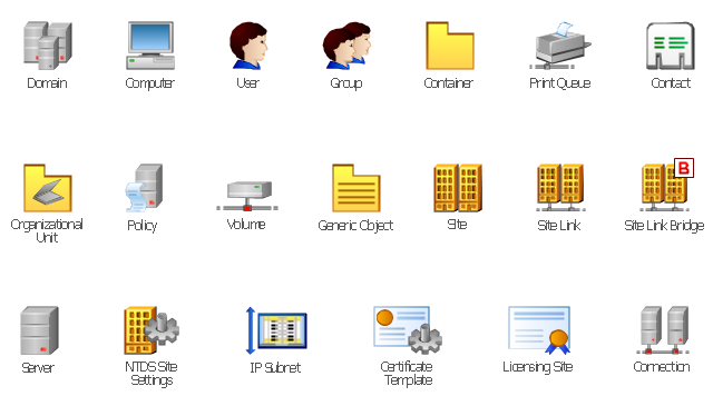
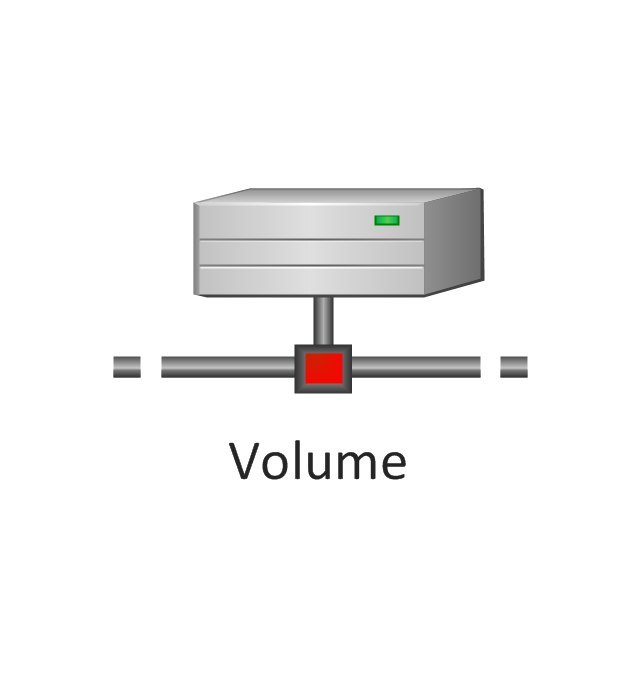
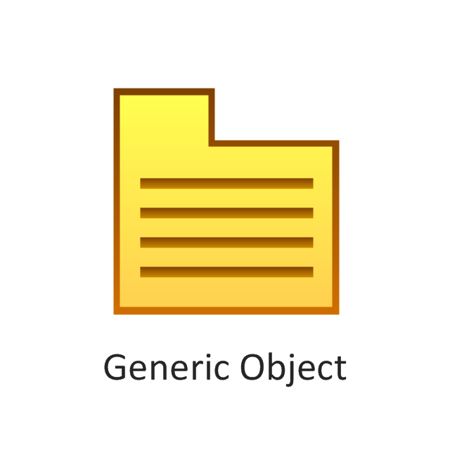
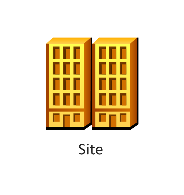
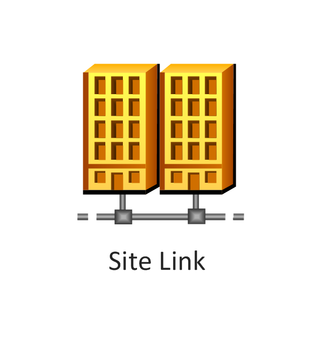
The vector stencils library "Active Directory" contains 20 symbols of Active Directory objects for drawing AD network diagrams. It helps network and system administrators to visualize Microsoft Windows Active Directory structures for network design, installation and maintainance.
"Objects.
An Active Directory structure is an arrangement of information about objects. The objects fall into two broad categories: resources (e.g., printers) and security principals (user or computer accounts and groups). Security principals are assigned unique security identifiers (SIDs).
Each object represents a single entity - whether a user, a computer, a printer, or a group - and its attributes. Certain objects can contain other objects. An object is uniquely identified by its name and has a set of attributes - the characteristics and information that the object represents - defined by a schema, which also determines the kinds of objects that can be stored in Active Directory.
The schema object lets administrators extend or modify the schema when necessary. However, because each schema object is integral to the definition of Active Directory objects, deactivating or changing these objects can fundamentally change or disrupt a deployment. Schema changes automatically propagate throughout the system. Once created, an object can only be deactivated - not deleted. Changing the schema usually requires planning. Sites are implemented as a set of well-connected subnets." [Active Directory. Wikipedia]
The shapes example "Design elements - Active Directory" was created using the ConceptDraw PRO diagramming and vector drawing software extended with the Active Directory Diagrams solution from the Computer and Networks area of ConceptDraw Solution Park.
The vector stencils library "Active Directory" contains 20 symbols of Active Directory elements for drawing AD network diagrams. It helps network and system administrators to visualize Microsoft Windows Active Directory structures for network design, installation and maintainance.
"An Active Directory structure is an arrangement of information about objects. The objects fall into two broad categories: resources (e.g., printers) and security principals (user or computer accounts and groups). Security principals are assigned unique security identifiers (SIDs).
Each object represents a single entity - whether a user, a computer, a printer, or a group - and its attributes. Certain objects can contain other objects. An object is uniquely identified by its name and has a set of attributes - the characteristics and information that the object represents - defined by a schema, which also determines the kinds of objects that can be stored in Active Directory.
The schema object lets administrators extend or modify the schema when necessary. However, because each schema object is integral to the definition of Active Directory objects, deactivating or changing these objects can fundamentally change or disrupt a deployment. Schema changes automatically propagate throughout the system. Once created, an object can only be deactivated - not deleted. Changing the schema usually requires planning. Sites are implemented as a set of well-connected subnets." [Active Directory. Wikipedia]
The AD symbols example "Active Directory - Vector stencils library" was created using the ConceptDraw PRO diagramming and vector drawing software extended with the Active Directory Diagrams solution from the Computer and Networks area of ConceptDraw Solution Park.
www.conceptdraw.com/ solution-park/ active-directory-diagrams
- Lighting and switch layout | Design elements - Electrical and telecom
- Design elements - Electrical circuits | Design elements - Resistors ...
- Electrical Drawing Software | How To use House Electrical Plan ...
- Electrical Installation Symbol
- How To use Switches in Network Diagram | Cisco Network Objects ...
- Cisco Switches and Hubs. Cisco icons , shapes, stencils and symbols
- Drawing Symbols For Electrical Installation In Building
- Cisco Switches and Hubs. Cisco icons , shapes, stencils and symbols
- Cisco Network Topology. Cisco icons , shapes, stencils and symbols ...
- Cisco Switches and Hubs. Cisco icons , shapes, stencils and symbols
- Drawing Electrical Symbols
- Design elements - Cisco LAN | Cisco LAN. Cisco icons , shapes
- How To use Switches in Network Diagram | Cisco Switches and ...
- Application server rack diagram
- Power socket outlet layout | Outlets - Vector stenvils library ...
- Cisco Network Design. Cisco icons , shapes, stencils, symbols and ...
- Network Topology Graphical Examples | Hotel Network Topology ...
- Network Layout | Ethernet local area network layout floor plan ...
- Cisco Network Topology. Cisco icons , shapes, stencils and symbols ...
- Electrical Engineering | How to Create an Electrical Diagram ...
