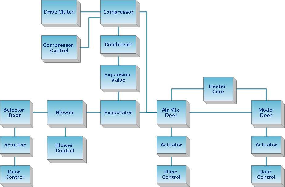
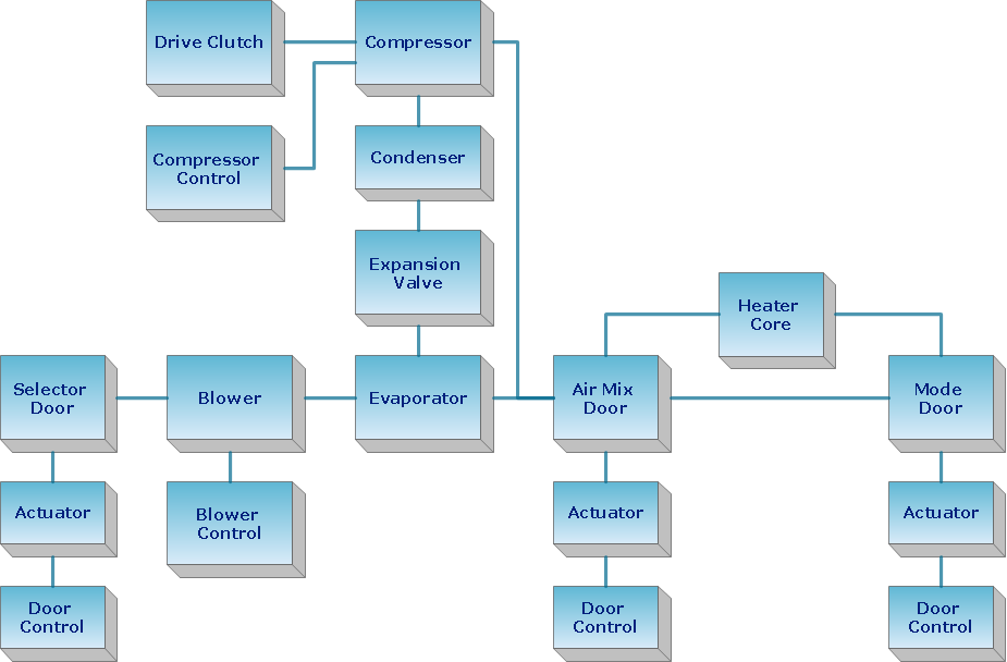
"HVAC (stands for Heating, Ventilation and Air Conditioning) is a control system that applies regulation to a heating and/ or air conditioning system. Usually a sensing device is used to compare the actual state (e.g., temperature) with a target state. Then the control system draws a conclusion what action has to be taken (e.g., start the blower).
More complex HVAC systems can interface to Building Automation System (BAS) to allow the building owners to have more control over the heating or cooling units. The building owner can monitor the system and respond to alarms generated by the system from local or remote locations." [HVAC control system. Wikipedia]
The vector stencils library "HVAC control equipment" contains 48 symbols of heating, ventilation, air conditioning, refrigeration and automated building control equipment.
Use the design elements library HVAC control equipment to draw HVAC plans, schematic diagrams of heating, ventilation, air conditioning, refrigeration and automated building control systems, environmental control design building plans and equipment layouts using the ConceptDraw PRO diagramming and vector drawing software.
The shapes library HVAC control equipment is contained in the HVAC Plans solution from the Building Plans area of ConceptDraw Solution Park.
Process Flow Diagram Symbols
Chemical and Process Engineering Solution from the Engineering Area of ConceptDraw Solution Park is a unique tool which contains variety of predesigned process flow diagram symbols for easy creating various Chemical and Process Flow Diagrams in ConceptDraw PRO.Chemical Engineering
ConceptDraw PRO is a powerful diagramming and vector drawing software. Extended with Chemical and Process Engineering Solution from the Engineering Area of ConceptDraw Solution Park, it became the best Chemical Engineering software.
 Chemical and Process Engineering
This chemical engineering solution extends ConceptDraw PRO v.9.5 (or later) with process flow diagram symbols, samples, process diagrams templates and libraries of design elements for creating process and instrumentation diagrams, block flow diagrams (BFD
ConceptDraw Arrows10 Technology
How should diagramming software work? The answer is - Fast and easy. "Tree"- mode drawing works like that. Just select objects in your drawing and press Tree or Chain button to connect all of them just in one click. Your diagram looks professional and it took only a moment to draw.Create Block Diagram
Block diagrams solution extends ConceptDraw PRO software with templates, samples and libraries of vector stencils for creating the block diagram. Create block diagrams, electrical circuit diagrams, schematics, and more in minutes with ConceptDraw PRO.Functional Block Diagram
You need design the Functional Block Diagram and dream to find the useful tools to draw it easier, quickly and effectively? ConceptDraw PRO offers the Block Diagrams Solution from the "What is a Diagram" Area which will help you!- Air Blower Symbols In Pid
- Blower Symbol For Schematic
- Process Flow Diagram Symbols | Blower Air P
- Symbol Blower On Drawing
- Blower Symbol
- Engineering Symbols For Blower
- Hot Air Blower Schematic Diagr
- Blower Symble
- Air Schematic Symbols
- Pid Symbols
- Symbol Drawing Blower
- Mechanical Drawing Symbols | Process Flow Diagram Symbols ...
- Refrigerant Dryers Alarms Symbols
- Air Eliminator Symbol
- The Symbol For Rotary Filter In Chemical Engineering
- How to Create a HVAC Plan | HVAC Plans | Air handler- HVAC plan ...
- Engineer Design Air Blower Nozzle
- Electrical Symbols , Electrical Diagram Symbols | HVAC control ...
- Air Conditioning
- Air Blower Block Diagram


