How To use House Electrical Plan Software


This vector stencils library contains 195 cloud computing icons.
Use it to design cloud computing infographic and diagrams with ConceptDraw PRO software.
"Cloud computing, also on-demand computing, is a kind of Internet-based computing that provides shared processing resources and data to computers and other devices on demand. It is a model for enabling ubiquitous, on-demand access to a shared pool of configurable computing resources (e.g., networks, servers, storage, applications and services), which can be rapidly provisioned and released with minimal management effort. Cloud computing and storage solutions provide users and enterprises with various capabilities to store and process their data in third-party data centers.
Cloud computing has become a highly demanded service or utility due to the advantages of high computing power, cheap cost of services, high performance, scalability, accessibility as well as availability." [Cloud computing. Wikipedia]
The vector stencils library "Cloud clipart" is included in the Cloud Computing Diagrams solution from the Computer and Networks area of ConceptDraw Solution Park.
Access point
Airport

Alert

Banknote

Banknote bundle
Banknote bundles
Backup

Bar chart
Big data
Book (closed)
-cloud-clipart---vector-stencils-library.png--diagram-flowchart-example.png)
Book (open)
-cloud-clipart---vector-stencils-library.png--diagram-flowchart-example.png)
Books

Box, close

Box, open

Braces
Brackets

Bug

Building

Bus

Cable connection
Calculator
Calendar

Car

CD/DVD

Check list

Check mark

Clock
Cloud

Cloud computing
Cloud database
Cloud hosting
Cloud storage

Code
Coffee cup

Coin

Coins stack
Coins stacks
Communication

Computer terminal
Console
CPU
Credit card

Cubes
Dashboard

Database
Databases
Datacenter
Dialog box
Dialog boxes

Document

Documents

Dollar sign

Download

Earth

Email

Equal sign
Ethernet jack
Ethernet plug
Euro sign

Exclamation mark

Eye
Feed symbol

Feedback

File

Files

Filter

Firewall

Flash drive
Folder

Folders

Gamepad

Gauge

Gear
Gears, 2
Gears, 3
Globe

Hacker

Hard drive

Heart

Heart rhythm

Home

Hosting
Hotel

House
Image

Info

IP phone
Jet

Key

Keyboard
Laptop

Lego
Letter

Light bulb

Lightning
Line chart
Linux penguin

List

Load balancer
Location mark
Lock, close

Lock, open

Lock and key

Log
Login

Logout
Magnifying glass

Mail

Map
Memory (RAM)
-cloud-clipart---vector-stencils-library.png--diagram-flowchart-example.png)
Microphone

Minus sign
Mobile phone
Monitor

Mouse
Movie

Music

Music player

Network
Network bus

Newspaper

NIC (Network interface controller)
-cloud-clipart---vector-stencils-library.png--diagram-flowchart-example.png)
Not found (Error 404)
-cloud-clipart---vector-stencils-library.png--diagram-flowchart-example.png)
Notebook
Office printer
Operator

Page

Pages

PC

Pencil

Photo

Photo camera

Pie chart
Platform
Plus sign

Pound sign

Printer
Puzzle

Puzzles, 2x2
Puzzles, 3x3
Question sign

Rackmount server

Router
Safe
Satellite

Satellite antenna
Schedule

Sensor
Server

Server rack
Shield
Ship
Shopping bag

Shopping basket

Shopping cart

Sign up

Smartphone
Social network
Software box
Sound

Spider
Spreadsheet
SSD
Star

Stars, 5

Stethoscope

Stickman

Stickmen

Suitcase

Support
Switch
Syringe

Tablet computer
Tools

Train
Truck

Truck 2
TV

Umbrella

Upload

User man

User woman

User profile

Video

Video camera

Video mail

Virtual disk

Virus

Wallet

Web camera

Wifi antenna
Wireless
Wrench

X cross symbol

Yen sign

The vector stencils library "Cisco network topology" contains 89 symbols of Cisco network devices and design elements for drawing computer network topology diagrams.
"There are two basic categories of network topologies:
(1) Physical topologies,
(2) Logical topologies.
The shape of the cabling layout used to link devices is called the physical topology of the network. This refers to the layout of cabling, the locations of nodes, and the interconnections between the nodes and the cabling. The physical topology of a network is determined by the capabilities of the network access devices and media, the level of control or fault tolerance desired, and the cost associated with cabling or telecommunications circuits.
The logical topology in contrast, is the way that the signals act on the network media, or the way that the data passes through the network from one device to the next without regard to the physical interconnection of the devices." [Network topology. Wikipedia]
The symbols example "Cisco network topology - Vector stencils library" was created using the ConceptDraw PRO diagramming and vector drawing software extended with the Cisco Network Diagrams solution from the Computer and Networks area of ConceptDraw Solution Park.
www.conceptdraw.com/ solution-park/ computer-networks-cisco
Router

Broadband router

Router firewall

Wireless router

Workgroup switch

ATM switch

ISDN switch

Multilayer switch

Protocol translator

Communications server

Transpath

Bridge

Terminal server

Route switch processor

Content engine (cache director)
-cisco-network-topology---vector-stencils-library.png--diagram-flowchart-example.png)
Management engine (ME 1100)
-cisco-network-topology---vector-stencils-library.png--diagram-flowchart-example.png)
Switch processor

ITP

Voice gateway

BBSM

ATA

SIP Proxy server

NetRanger

Cisco 1000

IP

System controller

ACE

Directory server

ADM

Cisco Unity Express

Unity server

Cisco security

CallManager

DSLAM

H.323

CDM (Content Distribution Manager)
-cisco-network-topology---vector-stencils-library.png--diagram-flowchart-example.png)
ICM

Access point

Wireless bridge

Wireless connectivity

Guard

Mobile access router

Carrier Routing System (CRS)
-cisco-network-topology---vector-stencils-library.png--diagram-flowchart-example.png)
Vault

Workstation

PC

Macintosh

Cloud, gold

Cloud, white

Cloud, standard color

Cisco security management

PBX

DPT

Government building

Headquarters, blue

Router in building

Man

Woman

Workgroup switch, subdued

Router, subdued

File server

Firewall, horizontal

Firewall, vertical

Firewall, vertical, subdued

Lock

Key

Lock and key

Car

Truck

File cabinet

Breakout box

Breakout box, blue

Host

Relational database

Modem

BBS (Bulletin Board System)
-cisco-network-topology---vector-stencils-library.png--diagram-flowchart-example.png)
Satellite

Satellite dish

UPS

RPS

MAU

PAD

PAD X.28

Diskette

Contact center

Page icon
Antenna

Antenna, blue

Radio tower

Cisco Network Topology. Cisco icons, shapes, stencils and symbols

The vector stencils library "Cisco network topology" contains 89 symbols of Cisco network devices and design elements for drawing computer network topology diagrams.
"There are two basic categories of network topologies:
(1) Physical topologies,
(2) Logical topologies.
The shape of the cabling layout used to link devices is called the physical topology of the network. This refers to the layout of cabling, the locations of nodes, and the interconnections between the nodes and the cabling. The physical topology of a network is determined by the capabilities of the network access devices and media, the level of control or fault tolerance desired, and the cost associated with cabling or telecommunications circuits.
The logical topology in contrast, is the way that the signals act on the network media, or the way that the data passes through the network from one device to the next without regard to the physical interconnection of the devices." [Network topology. Wikipedia]
The symbols example "Cisco network topology - Vector stencils library" was created using the ConceptDraw PRO diagramming and vector drawing software extended with the Cisco Network Diagrams solution from the Computer and Networks area of ConceptDraw Solution Park.
www.conceptdraw.com/ solution-park/ computer-networks-cisco
"There are two basic categories of network topologies:
(1) Physical topologies,
(2) Logical topologies.
The shape of the cabling layout used to link devices is called the physical topology of the network. This refers to the layout of cabling, the locations of nodes, and the interconnections between the nodes and the cabling. The physical topology of a network is determined by the capabilities of the network access devices and media, the level of control or fault tolerance desired, and the cost associated with cabling or telecommunications circuits.
The logical topology in contrast, is the way that the signals act on the network media, or the way that the data passes through the network from one device to the next without regard to the physical interconnection of the devices." [Network topology. Wikipedia]
The symbols example "Cisco network topology - Vector stencils library" was created using the ConceptDraw PRO diagramming and vector drawing software extended with the Cisco Network Diagrams solution from the Computer and Networks area of ConceptDraw Solution Park.
www.conceptdraw.com/ solution-park/ computer-networks-cisco
Router
Broadband router
Router firewall
Wireless router
Workgroup switch
ATM switch
ISDN switch
Multilayer switch
Protocol translator
Communications server
Transpath
Bridge
Terminal server
Route switch processor
Content engine (cache director)
Management engine (ME 1100)
Switch processor
ITP
Voice gateway
BBSM
ATA
SIP Proxy server
NetRanger
Cisco 1000
IP
System controller
ACE
Directory server
ADM
Cisco Unity Express
Unity server
Cisco security
CallManager
DSLAM
H.323
CDM (Content Distribution Manager)
ICM
Access point
Wireless bridge
Wireless connectivity
Guard
Mobile access router
Carrier Routing System (CRS)
Vault
Workstation
PC
Macintosh
Cloud, gold
Cloud, white
Cloud, standard color
Cisco security management
PBX
DPT
Government building
Headquarters, blue
Router in building
Man
Woman
Workgroup switch, subdued
Router, subdued
File server
Firewall, horizontal
Firewall, vertical
Firewall, vertical, subdued
Lock
Key
Lock and key
Car
Truck
File cabinet
Breakout box
Breakout box, blue
Host
Relational database
Modem
BBS (Bulletin Board System)
Satellite
Satellite dish
UPS
RPS
MAU
PAD
PAD X.28
Diskette
Contact center
Page icon
Antenna
Antenna, blue
Radio tower
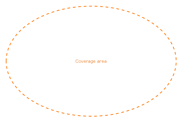
The vector stencils library "Local vehicular networking" contains 88 icon symbols for drawing local vehicular computer network diagrams.
"A vehicular ad hoc network (VANET) uses cars as mobile nodes in a MANET to create a mobile network. A VANET turns every participating car into a wireless router or node, allowing cars approximately 100 to 300 metres of each other to connect and, in turn, create a network with a wide range. As cars fall out of the signal range and drop out of the network, other cars can join in, connecting vehicles to one another so that a mobile Internet is created. It is estimated that the first systems that will integrate this technology are police and fire vehicles to communicate with each other for safety purposes." [Vehicular ad hoc network. Wikipedia]
The clip art example "Local vehicular networking - Vector stencils library" was created using the ConceptDraw PRO diagramming and vector drawing software extended with the Vehicular Networking solution from the Computer and Networks area of ConceptDraw Solution Park.
www.conceptdraw.com/ solution-park/ vehicular-networking
Cell Tower
Radio Tower
Satellite Dish

Antenna
In-vehicle Station
PC
Laptop Computer
IP Phone
Cell Phone
Router
Cloud
Coverage Area
Coverage Area 2
Car red
Car red (back view)
-local-vehicular-networking---vector-stencils-library.png--diagram-flowchart-example.png)
Car green
Car green (back view)
-local-vehicular-networking---vector-stencils-library.png--diagram-flowchart-example.png)
Car blue
Car blue (back view)
-local-vehicular-networking---vector-stencils-library.png--diagram-flowchart-example.png)
Taxi
Taxi (back view)
-local-vehicular-networking---vector-stencils-library.png--diagram-flowchart-example.png)
Truck
Truck (back view)
-local-vehicular-networking---vector-stencils-library.png--diagram-flowchart-example.png)
Airplane
Satellite
Ship
Traffic Light
Crosswalks

Bridge

Figure green

Figure blue

Figure purple
Figure red

Figure yellow

Figure white

Figure grey
House
Bungalow
Block
Office Building
High Rise Block
Factory
Factory (detailed)
-local-vehicular-networking---vector-stencils-library.png--diagram-flowchart-example.png)
Airport
Mote large

Fir Tree

Tree

Mountain

Lake

Local area network (LAN). Computer and Network Examples
 diagram")

The vector stencils library "Global networks" contains 63 computer and telecommunication icon symbols for drawing the global vehicular network diagrams.
"Satellite Internet access is Internet access provided through communications satellites. Modern satellite Internet service is typically provided to users through geostationary satellites that can offer high data speeds, with newer satellites achieving downstream data speeds up to 15 Mbps. ...
Satellite Internet generally relies on three primary components: a satellite in geostationary orbit (sometimes referred to as a geosynchronous Earth orbit, or GEO), a number of ground stations known as gateways that relay Internet data to and from the satellite via radio waves (microwave), and a VSAT (very-small-aperture terminal) dish antenna with a transceiver, located at the subscriber's premises. Other components of a satellite Internet system include a modem at the user end which links the user's network with the transceiver, and a centralized network operations center (NOC) for monitoring the entire system. Working in concert with a broadband gateway, the satellite operates a Star network topology where all network communication passes through the network's hub processor, which is at the center of the star. With this configuration, the number of remote VSATs that can be connected to the hub is virtually limitless." [Satellite Internet access. Wikipedia]
The clip art example "Global networks - Vector stencils library" was created using the ConceptDraw PRO diagramming and vector drawing software extended with the Vehicular Networking solution from the Computer and Networks area of ConceptDraw Solution Park.
www.conceptdraw.com/ solution-park/ vehicular-networking
City

Office Building

House

Radio Tower

Satellite Dish

International Space Station
Space Shuttle

Satellite

Satellite

Rocket

Airplane

Airplane

Airplane (back view)
-global-networks---vector-stencils-library.png--diagram-flowchart-example.png)
Airplane (back view)
-global-networks---vector-stencils-library.png--diagram-flowchart-example.png)
Helicopter

Helicopter

Helicopter (back view)
-global-networks---vector-stencils-library.png--diagram-flowchart-example.png)
Helicopter (back view)
-global-networks---vector-stencils-library.png--diagram-flowchart-example.png)
Car

Trailer

Double Decker Bus
High-speed Train

Freight Train

Regular Ship

Regular Ship

Passenger Vessel

Passenger Vessel

Battleship

Battleship

Submarine

Submarine

Bulk Carrier

Multipurpose Ship

Passanger Ship

Offshore Oil Platform

Eastern Hemisphere

Western Hemisphere

Eastern Hemisphere (oval)
-global-networks---vector-stencils-library.png--diagram-flowchart-example.png)
Western Hemisphere (oval)
-global-networks---vector-stencils-library.png--diagram-flowchart-example.png)
Eastern Hemisphere (oval)
-global-networks---vector-stencils-library.png--diagram-flowchart-example.png)
Western Hemisphere (oval)
-global-networks---vector-stencils-library.png--diagram-flowchart-example.png)
Orbit

Orbit (oval)
-global-networks---vector-stencils-library.png--diagram-flowchart-example.png)
Earth

Moon

Mars

World Map

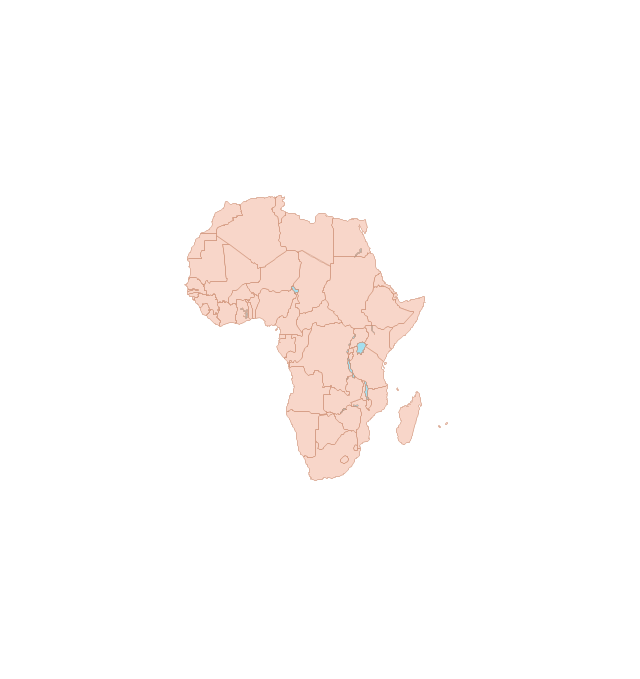
Africa
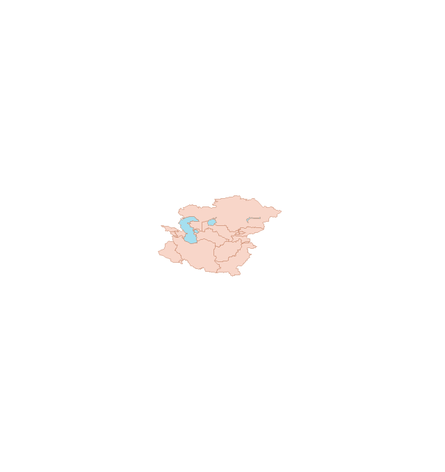
Central Asia
East Asia

Southern Asia

Middle East
Australia

Europe

Russia

South America
Central America

North America
Canada

USA
Cisco Network Icons
The vector stencils library "Cisco network topology" contains 89 symbols of Cisco network devices and design elements for drawing computer network topology diagrams.
"There are two basic categories of network topologies:
(1) Physical topologies,
(2) Logical topologies.
The shape of the cabling layout used to link devices is called the physical topology of the network. This refers to the layout of cabling, the locations of nodes, and the interconnections between the nodes and the cabling. The physical topology of a network is determined by the capabilities of the network access devices and media, the level of control or fault tolerance desired, and the cost associated with cabling or telecommunications circuits.
The logical topology in contrast, is the way that the signals act on the network media, or the way that the data passes through the network from one device to the next without regard to the physical interconnection of the devices." [Network topology. Wikipedia]
The symbols example "Cisco network topology - Vector stencils library" was created using the ConceptDraw PRO diagramming and vector drawing software extended with the Cisco Network Diagrams solution from the Computer and Networks area of ConceptDraw Solution Park.
www.conceptdraw.com/ solution-park/ computer-networks-cisco
"There are two basic categories of network topologies:
(1) Physical topologies,
(2) Logical topologies.
The shape of the cabling layout used to link devices is called the physical topology of the network. This refers to the layout of cabling, the locations of nodes, and the interconnections between the nodes and the cabling. The physical topology of a network is determined by the capabilities of the network access devices and media, the level of control or fault tolerance desired, and the cost associated with cabling or telecommunications circuits.
The logical topology in contrast, is the way that the signals act on the network media, or the way that the data passes through the network from one device to the next without regard to the physical interconnection of the devices." [Network topology. Wikipedia]
The symbols example "Cisco network topology - Vector stencils library" was created using the ConceptDraw PRO diagramming and vector drawing software extended with the Cisco Network Diagrams solution from the Computer and Networks area of ConceptDraw Solution Park.
www.conceptdraw.com/ solution-park/ computer-networks-cisco
Router
Broadband router
Router firewall
Wireless router
Workgroup switch
ATM switch
ISDN switch
Multilayer switch
Protocol translator
Communications server
Transpath
Bridge
Terminal server
Route switch processor
Content engine (cache director)
Management engine (ME 1100)
Switch processor
ITP
Voice gateway
BBSM
ATA
SIP Proxy server
NetRanger
Cisco 1000
IP
System controller
ACE
Directory server
ADM
Cisco Unity Express
Unity server
Cisco security
CallManager
DSLAM
H.323
CDM (Content Distribution Manager)
ICM
Access point
Wireless bridge
Wireless connectivity
Guard
Mobile access router
Carrier Routing System (CRS)
Vault
Workstation
PC
Macintosh
Cloud, gold
Cloud, white
Cloud, standard color
Cisco security management
PBX
DPT
Government building
Headquarters, blue
Router in building
Man
Woman
Workgroup switch, subdued
Router, subdued
File server
Firewall, horizontal
Firewall, vertical
Firewall, vertical, subdued
Lock
Key
Lock and key
Car
Truck
File cabinet
Breakout box
Breakout box, blue
Host
Relational database
Modem
BBS (Bulletin Board System)
Satellite
Satellite dish
UPS
RPS
MAU
PAD
PAD X.28
Diskette
Contact center
Page icon
Antenna
Antenna, blue
Radio tower
- Visio Stencil Antenna Tower
- Communications Tower Icon 3d
- Radio Tower Visio Stencil
- Cisco Network Topology. Cisco icons, shapes, stencils and symbols ...
- Electrical Tower Stencil For Visio
- Visio Stencil Radio Tower
- Microwave Icon In Telecom
- Cisco Network Topology. Cisco icons, shapes, stencils and symbols ...
- Diagram Of Telephome Tower
- Cell Tower Visio Stencil