Electrical Symbols — Logic Gate Diagram

The vector stencils library "Logic gate diagram" contains 17 logical element symbols.
Use these shapes for drawing the logic gate diagrams in the ConceptDraw PRO diagramming and vector drawing software extended with the Electrical Engineering solution from the Engineering area of ConceptDraw Solution Park.
www.conceptdraw.com/ solution-park/ engineering-electrical
Use these shapes for drawing the logic gate diagrams in the ConceptDraw PRO diagramming and vector drawing software extended with the Electrical Engineering solution from the Engineering area of ConceptDraw Solution Park.
www.conceptdraw.com/ solution-park/ engineering-electrical
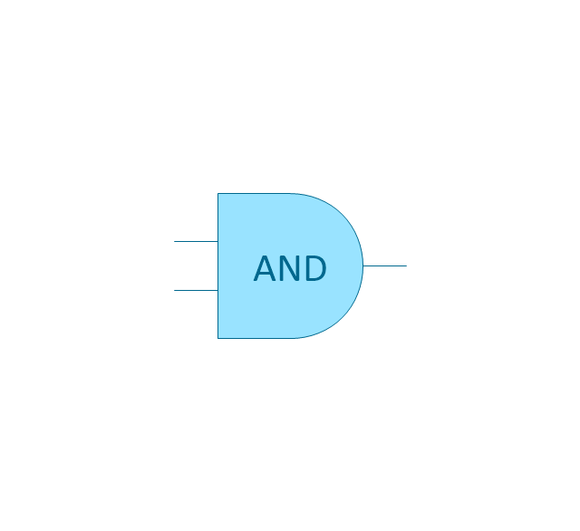
AND gate
OR gate

NOR gate (NOT OR)
-logic-gate-diagram---vector-stencils-library.png--diagram-flowchart-example.png)
NAND gate (NOT AND)
-logic-gate-diagram---vector-stencils-library.png--diagram-flowchart-example.png)
NOT gate (inverter)
-logic-gate-diagram---vector-stencils-library.png--diagram-flowchart-example.png)
EX-OR (Exclusive-OR) gate
-gate-logic-gate-diagram---vector-stencils-library.png--diagram-flowchart-example.png)
EX-NOR (Exclusive-NOR) gate
-gate-logic-gate-diagram---vector-stencils-library.png--diagram-flowchart-example.png)
Group

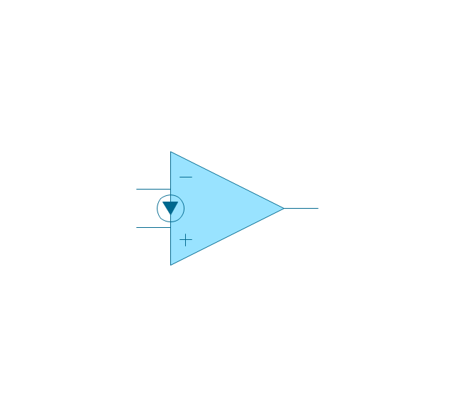
Operational Amplifier

Alternative Operational Amplifier

Norton op-amp
NOT gate (inverter)
-logic-gate-diagram---vector-stencils-library.png--diagram-flowchart-example.png)
NAND gate (NOT AND)
-logic-gate-diagram---vector-stencils-library.png--diagram-flowchart-example.png)
NOR gate (NOT OR)
-logic-gate-diagram---vector-stencils-library.png--diagram-flowchart-example.png)
Buffer

Gate with Open-Collector Output

Gate with Schmitt Trigger Input

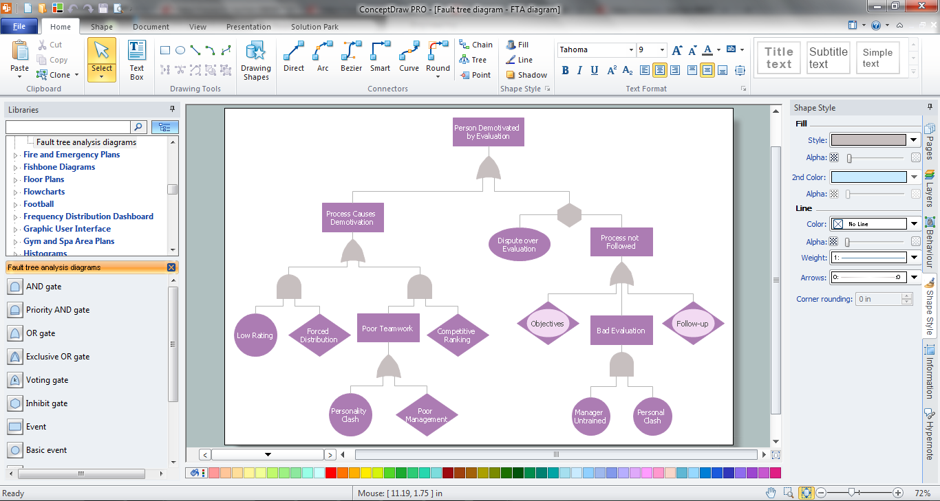
The vector stencils library "Fault tree analysis diagrams" contains 12 symbols for drawing FTA diagrams in the ConceptDraw PRO diagramming and vector drawing software extended with the Fault Tree Analysis Diagrams solution from the Engineering area of ConceptDraw Solution Park.
www.conceptdraw.com/ solution-park/ engineering-fault-tree-analysis-diagrams
www.conceptdraw.com/ solution-park/ engineering-fault-tree-analysis-diagrams
AND gate

Priority AND gate

OR gate

Inhibit gate

XOR gate

Event

Basic event

Undeveloped event

House event

Conditional event

Transfer symbol

Voting gate

The vector stencils library "Fault tree analysis diagrams" contains 12 symbols for drawing FTA diagrams in the ConceptDraw PRO diagramming and vector drawing software extended with the Fault Tree Analysis Diagrams solution from the Engineering area of ConceptDraw Solution Park.
www.conceptdraw.com/ solution-park/ engineering-fault-tree-analysis-diagrams
www.conceptdraw.com/ solution-park/ engineering-fault-tree-analysis-diagrams
AND gate
Priority AND gate
OR gate
Inhibit gate
XOR gate
Event
Basic event
Undeveloped event
House event
Conditional event
Transfer symbol
Voting gate
The vector stencils library "Logic gate diagram" contains 17 logical element symbols.
Use these shapes for drawing the logic gate diagrams in the ConceptDraw PRO diagramming and vector drawing software extended with the Electrical Engineering solution from the Engineering area of ConceptDraw Solution Park.
www.conceptdraw.com/ solution-park/ engineering-electrical
Use these shapes for drawing the logic gate diagrams in the ConceptDraw PRO diagramming and vector drawing software extended with the Electrical Engineering solution from the Engineering area of ConceptDraw Solution Park.
www.conceptdraw.com/ solution-park/ engineering-electrical
AND gate
OR gate
NOR gate (NOT OR)
NAND gate (NOT AND)
NOT gate (inverter)
EX-OR (Exclusive-OR) gate
EX-NOR (Exclusive-NOR) gate
Group
Operational Amplifier
Alternative Operational Amplifier
Norton op-amp
NOT gate (inverter)
NAND gate (NOT AND)
NOR gate (NOT OR)
Buffer
Gate with Open-Collector Output
Gate with Schmitt Trigger Input
The logic gate diagram example "2-bit ALU" was redesigned from the Wikimedia Commons file: 2-bit ALU.svg.
[commons.wikimedia.org/ wiki/ File:2-bit_ ALU.svg]
This file is licensed under the Creative Commons Attribution-Share Alike 3.0 Unported license. [creativecommons.org/ licenses/ by-sa/ 3.0/ deed.en]
"In digital electronics, an arithmetic and logic unit (ALU) is a digital circuit that performs integer arithmetic and logical operations. The ALU is a fundamental building block of the central processing unit of a computer, and even the simplest microprocessors contain one for purposes such as maintaining timers. The processors found inside modern CPUs and graphics processing units (GPUs) accommodate very powerful and very complex ALUs; a single component may contain a number of ALUs. ...
Most of a processor's operations are performed by one or more ALUs. An ALU loads data from input registers. Then an external control unit tells the ALU what operation to perform on that data, and then the ALU stores its result into an output register. The control unit is responsible for moving the processed data between these registers, ALU and memory." [Arithmetic logic unit. Wikipedia]
The logic gate diagram example "2-bit ALU" was created using the ConceptDraw PRO diagramming and vector drawing software extended with the Electrical Engineering solution from the Engineering area of ConceptDraw Solution Park.
Logic gate diagram

The vector stencils library "Fault tree analysis diagrams" contains 12 symbols for drawing FTA diagrams in the ConceptDraw PRO diagramming and vector drawing software extended with the Fault Tree Analysis Diagrams solution from the Engineering area of ConceptDraw Solution Park.
www.conceptdraw.com/ solution-park/ engineering-fault-tree-analysis-diagrams
www.conceptdraw.com/ solution-park/ engineering-fault-tree-analysis-diagrams
AND gate
Priority AND gate
OR gate
Inhibit gate
XOR gate
Event
Basic event
Undeveloped event
House event
Conditional event
Transfer symbol
Voting gate
Fault Tree Analysis Software
The vector stencils library "Fault tree analysis diagrams" contains 12 symbols for drawing FTA diagrams in the ConceptDraw PRO diagramming and vector drawing software extended with the Fault Tree Analysis Diagrams solution from the Engineering area of ConceptDraw Solution Park.
www.conceptdraw.com/ solution-park/ engineering-fault-tree-analysis-diagrams
www.conceptdraw.com/ solution-park/ engineering-fault-tree-analysis-diagrams
AND gate
Priority AND gate
OR gate
Inhibit gate
XOR gate
Event
Basic event
Undeveloped event
House event
Conditional event
Transfer symbol
Voting gate
- Draw Symbol Of Ex Or Gate
- Logic gate diagram - Vector stencils library | Symbol Ex Nor Gate
- Exclusive
- Electrical Symbols — Logic Gate Diagram | Logic gate diagram ...
- Amplifier - Circuit diagram | Electrical Symbols , Electrical Diagram ...
- Logic Gate Drawing
- Logic gate diagram - Template | Design elements - Logic gate ...
- Design elements - Logic gate diagram | Draw The Logic Gate Symbol
- 2-bit ALU - Logic gate diagram | Electrical Engineering | Electrical ...
- Xor Flow Digram