Mechanical Drawing Symbols

The vector stencils library "Bearings" contains 59 symbols of ball bearings, roller bearings, shafts, springs, gears, hooks, spindles, and keys.
Use it to design engineering drawings of machine tools and mechanical devices.
"A bearing is a machine element that constrains relative motion and reduce friction between moving parts to only the desired motion. The design of the bearing may, for example, provide for free linear movement of the moving part or for free rotation around a fixed axis; or, it may prevent a motion by controlling the vectors of normal forces that bear on the moving parts. Many bearings also facilitate the desired motion as much as possible, such as by minimizing friction. Bearings are classified broadly according to the type of operation, the motions allowed, or to the directions of the loads (forces) applied to the parts." [Bearing (mechanical). Wikipedia]
The shapes example "Design elements - Bearings" was created using the ConceptDraw PRO diagramming and vector drawing software extended with the Mechanical Engineering solution from the Engineering area of ConceptDraw Solution Park.
Bearing symbols

The vector stencils library "Dimensioning and tolerancing" contains 45 symbols of geometric dimensions and mechanical tolerances, geometric symbols, callouts, and text boxes and inserts.
Use these geometric dimensioning and tolerancing (GD&T) shapes to create annotated mechanical drawings in the ConceptDraw PRO diagramming and vector drawing software extended with the Mechanical Engineering solution from the Engineering area of ConceptDraw Solution Park.
www.conceptdraw.com/ solution-park/ engineering-mechanical
Datum (old)
-dimensioning-and-tolerancing---vector-stencils-library.png--diagram-flowchart-example.png)
Box callout

Datum symbol

Callout

All around callout

Text block

2 datum frame

Simple frame

Basic frame

1 datum frame

3 datum frame

Straightness

Flatness

Line profile

Circularity

Cylindricity

Surface profile

Position

Concentricity

Symmetry

Parallelism

Perpendicularity

Angularity

Material condition

Arc length

Diameter

Counterbore/ spotface

Countersink

Depth

Slope

Conical taper

Statistical tolerance

Datum (new)
-dimensioning-and-tolerancing---vector-stencils-library.png--diagram-flowchart-example.png)
Datum (new) 2
-2-dimensioning-and-tolerancing---vector-stencils-library.png--diagram-flowchart-example.png)
Target point

Target line

Target area (circle)
-dimensioning-and-tolerancing---vector-stencils-library.png--diagram-flowchart-example.png)
Target area (rectangle)
-dimensioning-and-tolerancing---vector-stencils-library.png--diagram-flowchart-example.png)
Total runout

Total runout 2

Circular runout

Circular runout 2

Surface finish

Surface finish, removal process

Surface finish, no process permitted

The vector stencils library "Fire and emergency planning" contains 52 symbols of firefighting equipment.
Use these shapes for drawing fire and emergency floor plans, equipment layouts, and evacuation schemes in the ConceptDraw PRO diagramming and vector drawing software extended with the Fire and Emergency Plans solution from the Building Plans area of ConceptDraw Solution Park.
www.conceptdraw.com/ solution-park/ building-fire-emergency-plans
Direction Arrow
Double Stairs
Stairs
Elevator

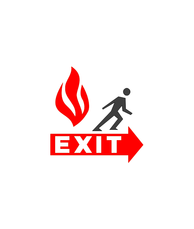
Emergency Exit
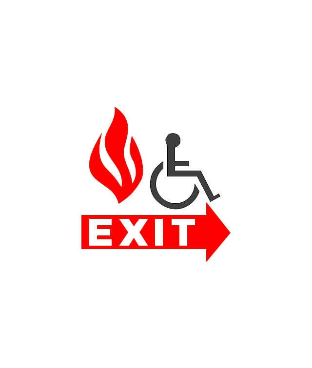
Handicapped Emergency Exit
Emergency Phone 1

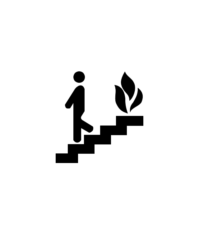
Use Stairs in Fire

Fire Escape or Fire Exit
Black Fire Alarm
Red Fire Alarm

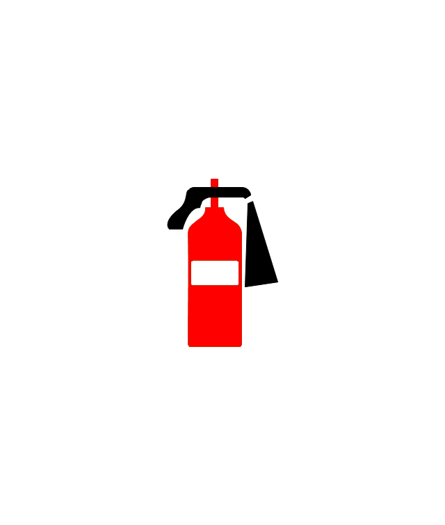
Fire Extinguisher 1
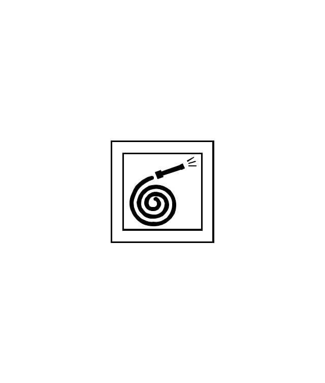
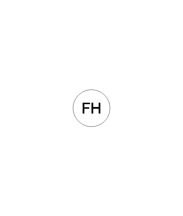
Fire Hose without text
Fire Extinguisher 2
Fire Hose with black text
Fire Hose with red text
First Aid
Left Arrow
Right Arrow
You are here
Biohazard
Radiation Hazard
Obstructions
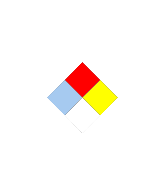
Hazardous Materials Storage
Sprinkler Connections

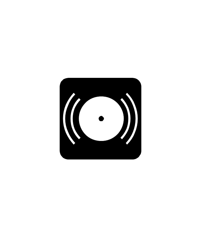
Private Fire Detection System
Exits and Entrances
Water Supplies

Elevator Shaft

Nearest Fire Hydrant
Electric Shut Off
Knox Box Location

Water Shut Off
Other Vertical Openings

Roof Access

Gas Shut Off

Emergency Phone 2
Emergency contact information
Fire Alarm
Fire Break Glass
Fire Escape

Danger Compressed Gas
Flammable Material
Oxidant Material
Harmful Chemicals
Non Ionising Radiation
Corrosive Material
High Voltage

Dangerous Chemical
Danger of Death
Fire Point
Fire Blanket

Building Plans with ConceptDraw DIAGRAM

Create Floor Plans Easily with ConceptDraw DIAGRAM


 Building Design Package
Architects and building engineers to develop building documentation, floor plans and building blueprints, to help designers depict bright and innovative design solutions, make beautiful design proposals and represent the most daring design ideas, to communicate ideas and concepts that relate to construction and design, explain requirements to a building contractor and builders, record completed work, and make a record of what currently exists.
- Shaft Machining Drawing Symbol
- Symbol For Bearing On Shaft
- Mechanical Drawing Symbols | Design elements - Bearings ...
- Shaft Symbol
- Mechanical Drawing Symbols | Design elements - Bearings | Design ...
- What A Symbol Of Shaft Feet
- Bearings - Vector stencils library | Mechanical Drawing Symbols ...
- Shaft Runout Roughness Symbol
- Design elements - Bearings | Threaded Shaft Drawing Symbol
- Mechanical Drawing Symbols | Mechanical Engineering | Design ...
- Mechanical Drawing Symbols | Shaft Representation Symbol In ...
- The Symbol For A Bearing
- Conventional Representation Or Symbol Of Bearing
- Mechanical Drawing Symbols | Mechanical Engineering | Electrical ...
- Design elements - Bearings | Flow chart Example. Warehouse ...
- Shaft Drawing Plan
- Conventional Symbol For Gear
- Mechanical Drawing Symbols | Design elements - Bearings | Valves ...
- Mechanical Drawing Symbols | Building Drawing Software for ...
- Mechanical Drawing Symbols | Design elements - Bearings ...