This site uses cookies. By continuing to browse the ConceptDraw site you are agreeing to our Use of Site Cookies.

Electrical Symbols — Transformers and Windings

A transformer is an electrical device that transfers electrical energy between two or more circuits through electromagnetic induction. Electromagnetic induction produces an electromotive force within a conductor which is exposed to time varying magnetic fields. Transformers are used to increase or decrease the alternating voltages in electric power applications. 26 libraries of the Electrical Engineering Solution of ConceptDraw DIAGRAM make your electrical diagramming simple, efficient, and effective. You can simply and quickly drop the ready-to-use objects from libraries into your document to create the electrical diagram.
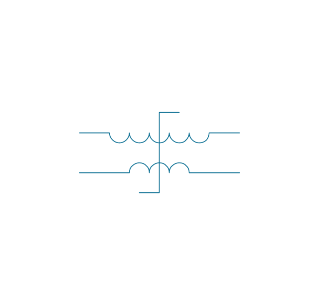
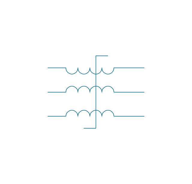
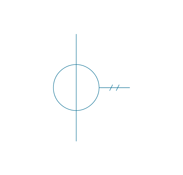
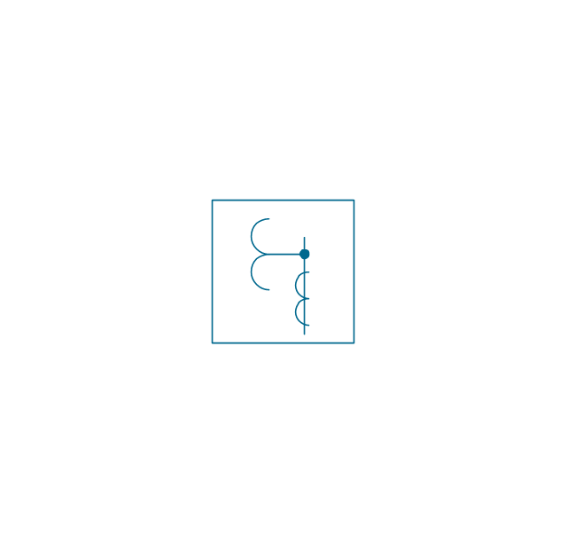
The vector stencils library "Transformers and windings" contains 29 element symbols of transformers, windings, couplers, metering devices, transductors, magnetic cores, chokes, and a variometer.
Use it to design the electromechanical device schematics and electronic circuit diagrams in the ConceptDraw PRO diagramming and vector drawing software extended with the Electrical Engineering solution from the Engineering area of ConceptDraw Solution Park.
www.conceptdraw.com/ solution-park/ engineering-electrical
Coaxial choke
Coaxial choke, coaxial choke, magnetic core,
Transductor
Transductor, transductor,
Saturating transformer
Saturating transformer, saturating transformer,
1-phase induction voltage regulator
1-phase induction voltage regulator, 1-phase, induction voltage regulator,
Triplex induction voltage regulator
Triplex induction voltage regulator, triplex, induction voltage regulator,
Induction voltage regulator
Induction voltage regulator, induction voltage regulator,
Current transformer 2
Current transformer 2, current transformer,
Current transformer 3
Current transformer 3, current transformer, bushing-type,
Potential transformer 2
Potential transformer 2, potential transformer,
Potential transformer with 3 windings
Potential transformer with 3 windings, potential transformer, winding,
Outdoor metering device
Outdoor metering device, outdoor metering device,
Linear coupler
Linear coupler, linear coupler,
Magnetic core, 1 line
Magnetic core, 1 line, magnetic core,
Magnetic core, 2 lines
Magnetic core, 2 lines, magnetic core,
Choke
Choke, choke, reactor,
Variometer
Variometer, variometer,
Air-core transformer
Air-core transformer, transformer, air-core,
Magnetic-core transformer
Magnetic-core transformer, transformer, magnetic-core,
Air-core transformer, 1 winding adjustable
Air-core transformer, 1 winding adjustable, transformer, air-core, 1 winding, adjustable,
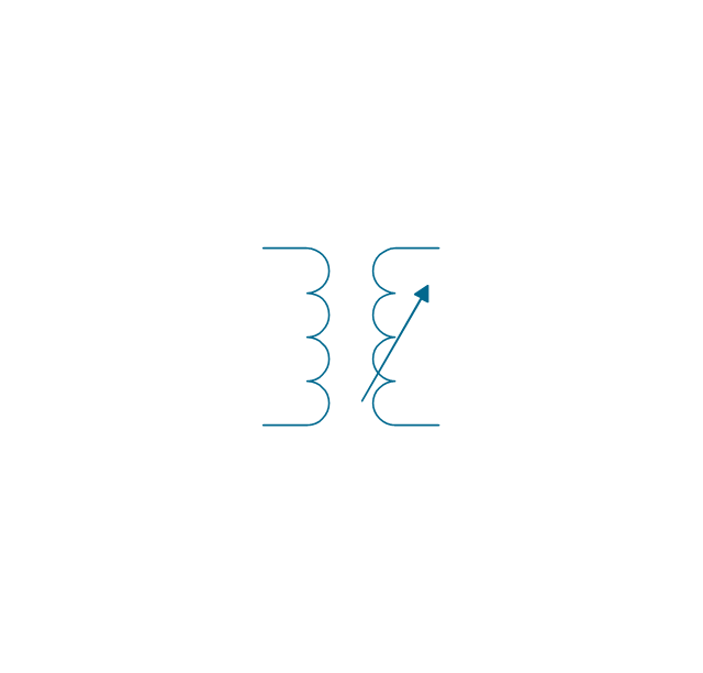
Magnetic-core transformer, 1 winding adjustable
Magnetic-core transformer, 1 winding adjustable, transformer, magnetic-core, 1 winding, adjustable,
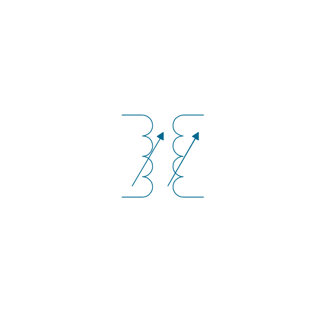
Air-core transformer, 2 windings adjustable
Air-core transformer, 2 windings adjustable, transformer, air-core, 2 windings, adjustable,
Magnetic-core transformer, 2 windings adjustable
Magnetic-core transformer, 2 windings adjustable, transformer, magnetic-core, 2 windings, adjustable,
Air-core transformer, mutual inductor
Air-core transformer, mutual inductor, transformer, air-core, mutual inductor,
Magnetic-core transformer, mutual inductor
Magnetic-core transformer, mutual inductor, transformer, magnetic-core, mutual inductor,
Transformer 2
Transformer 2, transformer,
Adjustable transformer, 1 winding
Adjustable transformer, 1 winding, adjustable transformer, 1 winding,
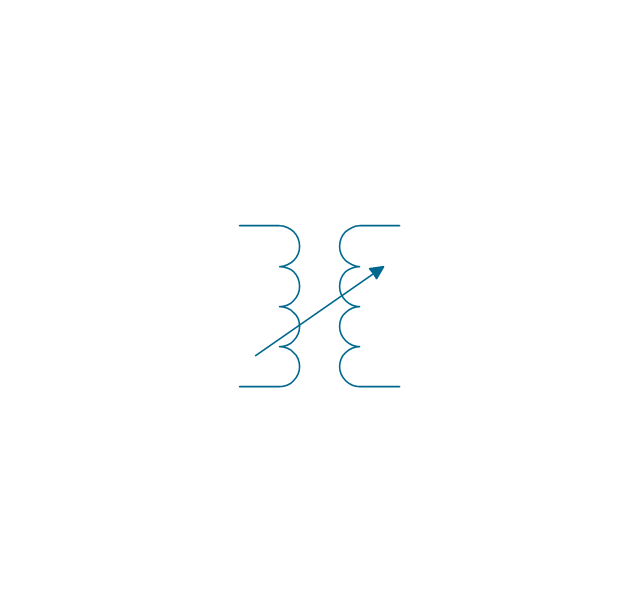
Adjustable transformer, mutual inductor
Adjustable transformer, mutual inductor, adjustable transformer,  mutual inductor,
Current transformer 1
Current transformer 1, current transformer,
Potential transformer
Potential transformer, potential transformer,

one-line diagram, single-line diagram, electrical diagram, engineering diagram, electrical symbol, one-line drawing One-line Diagrams

one-line diagram, single-line diagram, electrical diagram, engineering diagram, electrical symbol, one-line drawing
One-line Diagrams solution is a powerful electrical engineering tool to develop precise and detailed One-line Diagram, Single-line Diagram, Electrical diagram. This solution supplies the ConceptDraw DIAGRAM users with a wide set of vector libraries with special icons and electrical symbol elements for one-line drawing and electrical engineering diagram design including. It includes a large collection of samples of One-line Diagrams illustrating high-voltage and low-voltage systems, different electrical configurations and topologies, transmission systems, application of circuit breakers, protection electrical equipment, etc. It is perfect for all power-related workers, engineers, electricians, and other professionals working in power engineering and energy industries.

Electrical Diagram Symbols F.A.Q.
How to Use Electrical ConceptDraw Diagram Software

When drawing Electrical Schematics, Electrical Circuit Diagrams, Power Systems Diagrams, Circuit and Wiring Diagrams, Digital and Analog Logic Schemes, you will obligatory need the electrical symbols and pictograms to represent various electrical and electronic devices, such as resistors, wires, transistors, inductors, batteries, switches, lamps, readouts, amplifiers, repeaters, relays, transmission paths, semiconductors, generators, and many more. Today these symbols are internationally standardized, so the diagrams designed using them are recognizable and comprehensible by specialists from different countries. Electrical Engineering Solution included to ConceptDraw Solution Park provides 26 libraries with 926 commonly used electrical schematic and electrical engineering symbols making the reality the easy drawing of Electrical diagrams, schematics and blueprints. Now you need only a few minutes to create great-looking Electrical diagram, simply choose required electrical design elements from the libraries, drag them on the needed places at the document and connect in a suitable way.

energy icons, electrical power industry, industry icons, industry symbols, renewable energy industry, electrical substation diagram Energy Industry Infographics

energy icons, electrical power industry, industry icons, industry symbols, renewable energy industry, electrical substation diagram
Energy Industry Infographics solution is ideal for designing energy-related business infographics, diagrams, charts, illustrations for documents and presentations. It provides a set of libraries with special vector energy industry symbols, icons for electrical power industry, nuclear power industry, fossil fuel industry, and renewable energy industry, energy icons of fuel gas, liquid fuel, solid fuel, industry icons of electrical substations, power plants. Collection of samples including nuclear fuel cycle and energy distribution schematics, electrical substation diagram, energy intelligence dashboard, electricity grid schematics, and many more is also included. This solution is indispensable for all engineers, chefs, managers, marketers, and other professionals working in energy industry.

Electrical Symbols, Electrical Schematic Symbols

Electrical Schematics and Electrical Circuit Diagrams are included to the number of obligatory diagrams and documents while developing the package of construction documentation for the building project. It is comfortable to use the special drawing software for designing diagrams of this type. ConceptDraw DIAGRAM diagramming and vector drawing software extended with Electrical Engineering solution from Industrial Engineering Area of ConceptDraw Solution Park provides the powerful drawing tools, a lot of specific samples and templates, and numerous libraries with incredibly large quantity of predesigned electrical schematic symbols, including analog and digital logic electrical symbols, electrical circuits symbols, inductors, power sources, lamps, resistors, transistors, delay elements, switches and relays, terminals and connectors, and many other useful electrical symbols, which will be helpful for easy designing professional looking Electrical Schematics, Electrical Engineering Diagrams, Circuit and Wiring Diagrams, Power Systems Diagrams, Digital and Analog Logic Schematics.

What Is a Circle Spoke Diagram

What Is a Circle Spoke Diagram? It is a diagram which have a central item surrounded by other items in a circle. The Circle Spoke Diagrams are often used to show the features or components of the central item in marketing and management documents and presentations. ConceptDraw DIAGRAM extended with Business Diagrams Solution from the Management Area is the best software for creating Circle-Spoke Diagrams.

How to Make Audio and Video Connections

Use the ConceptDraw DIAGRAM software that has vector clipart of numerous cable connectors, examples, and templates for drawing different types of audio and video connection diagrams. Paste icon of the receiver or another device to page and layout sockets and plugs. Further connect plugs with each other, and now you have well-designed connection diagram.

electron tube circuit, vacuum tube, gas-filled tube, electrical engineering, electrical symbols, wiring diagram, diode symbol, circuit diagram,  electrical schematic Electron Tube Circuits

electron tube circuit, vacuum tube, gas-filled tube, electrical engineering, electrical symbols, wiring diagram, diode symbol, circuit diagram,  electrical schematic
Basic Circuit Diagrams solution extends the functionality of ConceptDraw DIAGRAM software is effective for electrical engineering, designing, circuit diagrams, electrical schematics, wiring diagrams, electronic schematics, and more.

Electrical Symbols — Transistors

A transistor is a semiconductor device used to amplify or switch electronic signals and electrical power. It is composed of semiconductor material usually with at least three terminals for connection to an external circuit. A voltage or current applied to one pair of the transistor's terminals changes the current through another pair of terminals. Because the controlled (output) power can be higher than the controlling (input) power, a transistor can amplify a signal. Today, some transistors are packaged individually, but many more are found embedded in integrated circuits. 26 libraries of the Electrical Engineering Solution of ConceptDraw DIAGRAM make your electrical diagramming simple, efficient, and effective. You can simply and quickly drop the ready-to-use objects from libraries into your document to create the electrical diagram.

AWS

The AWS diagrams are convenient way for explaining the work of Amazon Web Services. ConceptDraw DIAGRAM diagramming and vector drawing software offers the AWS Architecture Diagrams Solution from the Computer and Networks Area for fast and easy creating the AWS diagrams of any complexity.

Electrical Symbols — IGFET

There are several types of insulated gate field-effect transistors (IGFETs) in common use. The early term metal oxide semiconductor field-effect transistor (MOSFET) is still in use, and MOSFET is usually acceptable as a generic term for IGFETs. The metal oxide, and the insulation in the IGFET, is the insulating material between the gate terminal and the substrate between the source and drain terminals. This insulator must have very low leakage, of course, but another requirement for good performance of the transistor is that the dielectric constant of the material must be very high. 26 libraries of the Electrical Engineering Solution of ConceptDraw DIAGRAM make your electrical diagramming simple, efficient, and effective. You can simply and quickly drop the ready-to-use objects from libraries into your document to create the electrical diagram.

Electrical Symbols — Switches and Relays

In electrical engineering, a switch is an electrical component that can break an electrical circuit, interrupting the current or diverting it from one conductor to another. The mechanism of a switch may be operated directly by a human operator to control a circuit (for example, a light switch or a keyboard button), may be operated by a moving object such as a door-operated switch, or may be operated by some sensing element for pressure, temperature or flow. A relay is a switch that is operated by electricity. Switches are made to handle a wide range of voltages and currents; very large switches may be used to isolate high-voltage circuits in electrical substations. 26 libraries of the Electrical Engineering Solution of ConceptDraw DIAGRAM make your electrical diagramming simple, efficient, and effective. You can simply and quickly drop the ready-to-use objects from libraries into your document to create the electrical diagram.

BPMN 2.0

ConceptDraw DIAGRAM diagramming and vector drawing software offers the Business Process Diagram Solution from the Business Processes Area of ConceptDraw Solution Park with powerful tools to help you easy represent the business processes and create the business process diagrams based on BPMN 2.0 standard.

home appliances, electrical symbols, home automation, light switches, wiring diagram symbols, electrical schematic, electrical diagram Home Automation and Wiring

home appliances, electrical symbols, home automation, light switches, wiring diagram symbols, electrical schematic, electrical diagram
Develop modern solutions for home automation, construct electrical plans and electronic wiring diagrams, design electrical diagram for a smart home system, implement innovations and modern technologies, and describe wiring simply and professionally with ConceptDraw DIAGRAM and Home Automation and Wiring solution. It includes a lot of practical examples of home automation and wiring, and a large collection of vector stencils of home automation equipment, alarm and security equipment, home appliances, electrical symbols, light switches, plugs, sockets, wiring diagram symbols, and more. Home Automation and Wiring solution is the best way to make your home smart still the planning stage and construction of your home electrical schematic.

One-line Diagram

One-line diagram also known as a Single-line diagram is a type of graphic representation of an electrical circuit or system. ConceptDraw's One-line Diagrams solution offers powerful tools for designing accurate, intuitive, and up-to-date One-line diagrams. Create innovative electrical engineering schematics to give an accurate picture of the electrical systems, generate reports about the engineering studies and research, design educational materials, identify potential sources of electric energy, analyze systems and track bottlenecks fast and easily. The included collection of predesigned vector objects and samples provides the simplicity and rapidity of drawing.

Transmission Lines

A transmission line is an electrical engineering term used for a specialized cable (conductor), which conducts electromagnetic waves and carries a large amount of high-voltage electrical power from the generating substation to various distribution units. Striving to find effective software to develop electrical equipment and create professional-looking Electrical Circuits, turn your attention to ConceptDraw DIAGRAM software enhanced with Power Сircuits solution. It includes powerful drawing tools, illustrative samples, and large collection of vector design elements of transmission lines electrical distribution, transmitters, switches, transformers, electrical motors, electric generators, and many more.

Single-line Diagram

Single-line diagram (SLD) also known as a One-line diagram is a simplest symbolic representation of a portion or entire electric power system. It is helpful for both the development and maintenance of electrical system, troubleshooting, rerouting power after faults, and changing system configurations in order to increase its performance, reliability, and safety. ConceptDraw's One-line Diagrams solution offers powerful tools to create Single-line diagrams of any complexity, reflect the facility’s electrical distribution system and show how incoming power is distributed to equipment in an electrical circuit. Study and evaluate effectively the short-circuit, arc flash, and electrical safety; develop, install and maintain the electrical system.

electrical diagram, electrical engineering, electrical schematic, electrical schematic symbols, electrical diagram symbols  Electrical Engineering

electrical diagram, electrical engineering, electrical schematic, electrical schematic symbols, electrical diagram symbols
The Electrical Engineering solution is known to be extending the ConceptDraw DIAGRAM application with a wide range of electrical schematic symbols, electrical engineering examples, electrical diagram symbols, the pre-made templates and stencil libraries full of the electrical engineering-related design elements. All listed can help all the ConceptDraw DIAGRAM users to design the needed electrical schematics, either analog or digital logic, wiring and circuit schematics and diagrams, maintenance and repair diagrams and power systems diagrams so they can be used both in the electronics and electrical engineering field of business activity.

ConceptDraw Solution Park ConceptDraw Solution Park

ConceptDraw Solution Park
ConceptDraw Solution Park collects graphic extensions, examples and learning materials