HelpDesk
How to Draw a Chemical Process Flow Diagram
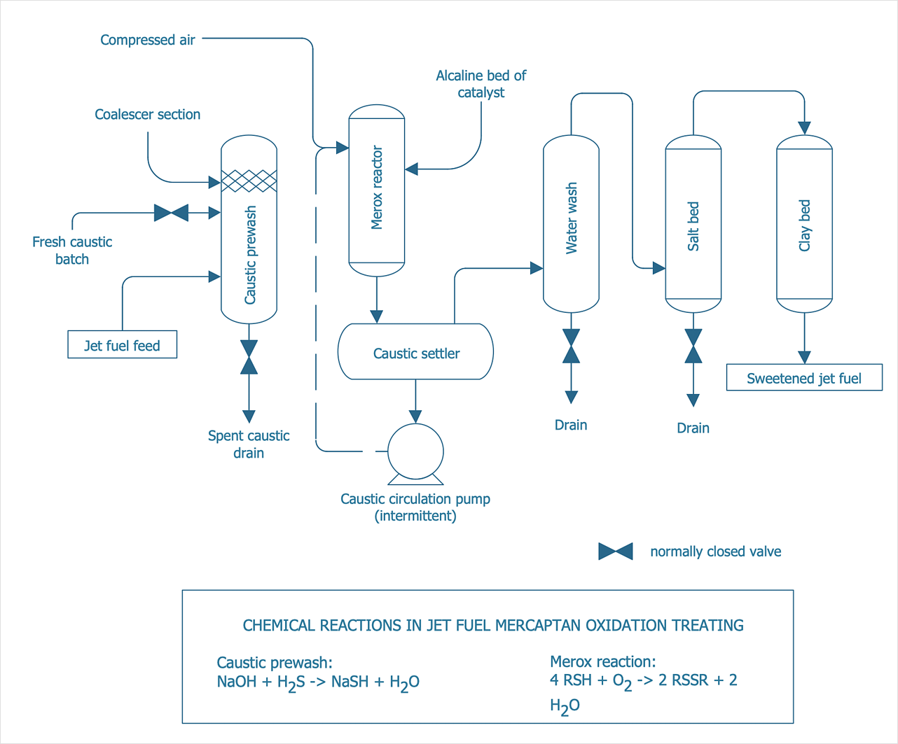
Process Flow Diagram widely used in modeling of processes in the chemical industry. A Chemical Process Flow diagram (PFD) is a specialized type of flowchart. With the help of Chemical Process Flow Diagram engineers can easily specify the general scheme of the processes and chemical plant equipment. Chemical Process Flow Diagram displays the real scheme of the chemical process, the relationship between the equipment and the technical characteristics of the process. Chemical Process Flow Diagram illustrates the connections between the basic equipment as well as the overall structure of pipelines and other supporting equipment. The purpose of the PFD is to build the image of the basic idea of the chemical process. ConceptDraw DIAGRAM together with its Chemical and Process Engineering solution delivers the possibility to design Chemical Process Flow diagrams. It is designed for chemical industry engineers and designers.- Drawing Symbol Used In Industry
- Design Symbol In Industry
- Mechanical Engineering Drawing Symbol In Pdf Of Industries
- Various Design Symbol Used In Industry Drawing
- Drawing Symbols Industry
- Mechanical Drawing Symbols | Process Flowchart | CAD Drawing ...
- Process Flowchart | Mechanical Drawing Symbols | Fishbone ...
- Mechanical Drawing Symbols | Process Flowchart | Design ...
- Mechanical Drawing Symbols | Process Flow Diagram Symbols ...
- Automobile Industry Engineering Drawing Symbols
- Mechanical Drawing Symbols
- Automobile Industry Drawing Symbols
- Process Flowchart | How to Draw a Chemical Process Flow Diagram ...
- Symbol For Industry Use Quality
- Symbols Of Basic Mechanical In Industry
- Drawing Symbol In Mechanical Industry
- Drawing Symbols Used In The Building Industry
- Mechanical Drawing Symbols | CAD Drawing Software for Making ...
- Equipments And Their Symbols In Chemical Industry
- Process Flowchart | Mechanical Drawing Symbols | CAD Drawing ...
