 Mechanical Engineering
This solution extends ConceptDraw PRO v.9 mechanical drawing software (or later) with samples of mechanical drawing symbols, templates and libraries of design elements, for help when drafting mechanical engineering drawings, or parts, assembly, pneumatic,
IDEF3 Standard
Use Case Diagrams technology. IDEF3 Standard is intended for description and further analysis of technological processes of an enterprise. Using IDEF3 standard it is possible to examine and model scenarios of technological processes.HelpDesk
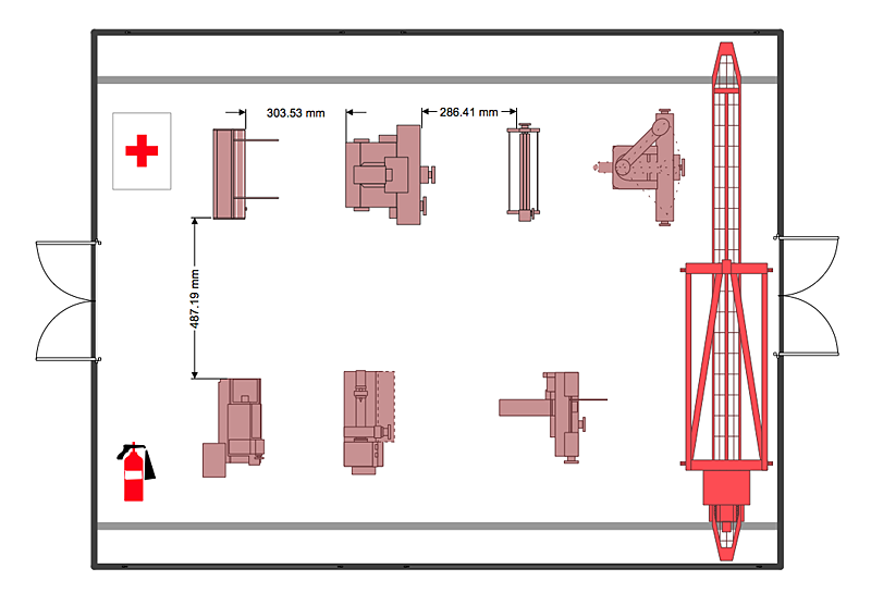
How to Create a Plant Layout Design
A plant construction process begins from a plant layout stage - an engineering stage used to design, analyze and finally choose the suitable configurations for a manufacturing plant. Plant Layout issues are core to any enterprise and are challenged in all types of manufacturing process. The sufficiency of layout influences the efficiency of subsequent operations. It is an important background for efficient manufacturing and also has a great deal with many questions. Once the place of the plant has been determined, the next important task before the management of the plant is to plan appropriate layout for the enterprise. Plant layout is used to create the most effective physical arrangement of machinery and equipment, with the plant building in such a manner so as to make quickest and cheapest way from a raw material to the shipment of the completed product Making a plan that shows the location of industrial equipment involves many different elements that can be managed using ConHelpDesk
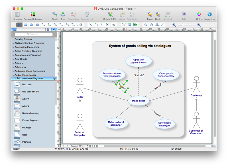
How to Add Text to a Connector in ConceptDraw PRO
The new ConceptDraw Arrows10 Technology is a powerful diagramming technique that powered the way business drawing created. ConceptDraw PRO gives you some tools for connecting shapes: Direct Connectors, Smart, Arc, Bezier, Curve and Round Connectors.Direct Connectors are direct lines from the point to the point. Smart , Arc, Bezier, Curve and Round Connectors are almost the same as Direct Connectors. However, they automatically move around other objects. You can use Chain, or Tree connection mode for connection of multiple objects with any type of connectors. ConceptDraw PRO allows you to add and move text on a connector the same way that you add and move text on other any object.- Mechanical Drawing Symbols | Design elements - Dimensioning ...
- Mechanical Drawing Symbols | Design elements - Dimensioning ...
- Mechanical Drawing Symbols | Design elements - Dimensioning ...
- Mechanical Drawing Symbols | Process Flow Diagram Symbols ...
- Tolerances And Surface Finish On Engineering Drawings
- Mechanical Drawing Symbols | Process Flow Diagram Symbols ...
- Design elements - Bearings | Mechanical Drawing Symbols ...
- Mechanical Drawing Symbols | Mechanical Drawing Software ...
- Surface Finish Symbol Engineering Drawing
- Technical Drawing Software | How to Create a Mechanical Diagram ...
- Mechanical Drawing Symbols | Mechanical Drawing Software ...
- Mechanical Drawing Symbols | Design elements - Bearings ...
- Mechanical Drawing Symbols | Mechanical Engineering ...
- Mechanical Drawing Symbols | Process Flowchart | Technical ...
- Mechanical Drawing Symbols | Design elements - Dimensioning ...
- Accuracy Dimension Symbol
- Technical Drawing Software | Building Drawing Design Element Site ...
- Mechanical Drawing Symbols | Electrical Symbols — Rotating ...
- Engg Drawing All Geometric Symbols With Meaning
- Mechanical Drawing Symbols | Elements location of a welding ...


