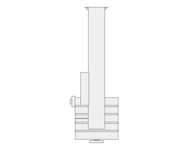
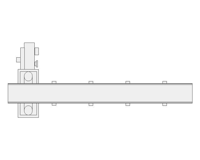
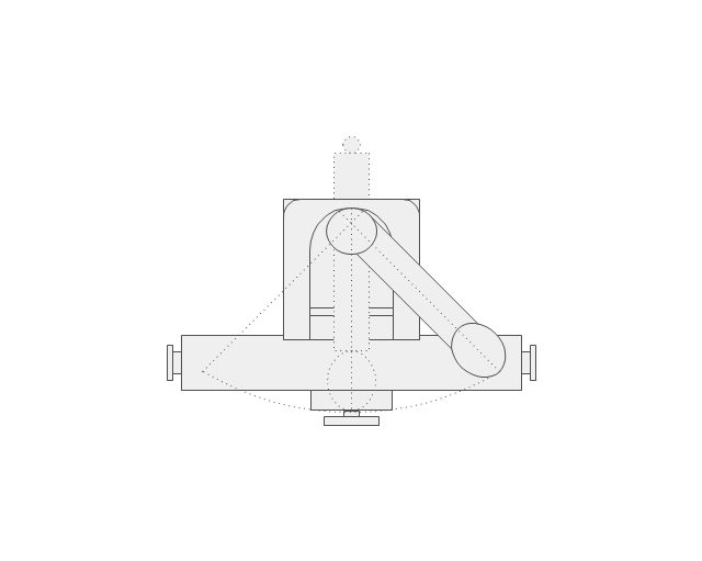
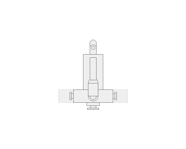
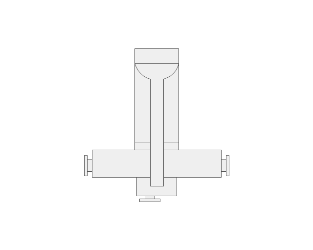
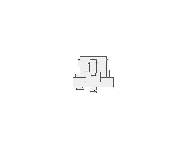
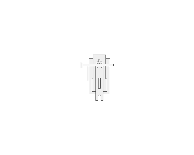
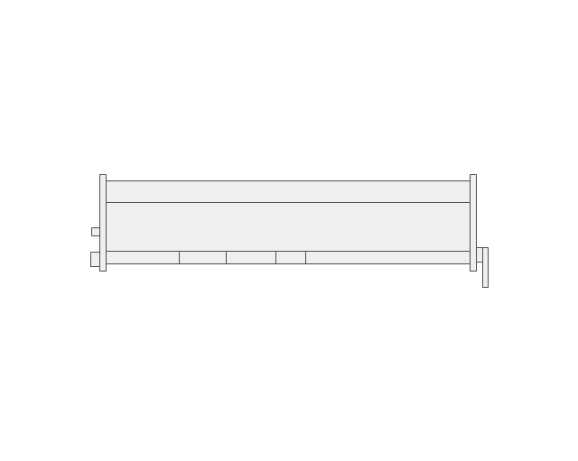
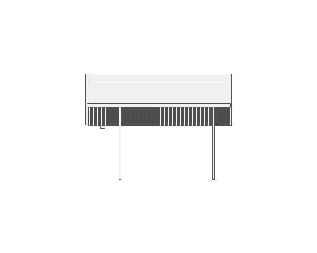
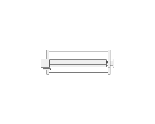
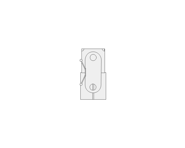
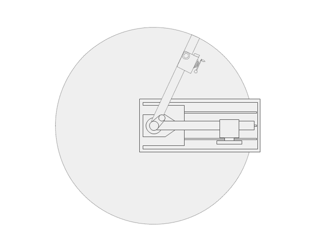
This technical drawing shows the machine parts assembly using joining by threaded fasteners.
"Assembling (joining of the pieces) is done by welding, binding with adhesives, riveting, threaded fasteners, or even yet more bending in the form of a crimped seam. Structural steel and sheet metal are the usual starting materials for fabrication, along with the welding wire, flux, and fasteners that will join the cut pieces. As with other manufacturing processes, both human labor and automation are commonly used. The product resulting from fabrication may be called a fabrication. Shops that specialize in this type of metal work are called fab shops. The end products of other common types of metalworking, such as machining, metal stamping, forging, and casting, may be similar in shape and function, but those processes are not classified as fabrication." [Metal fabrication. Wikipedia]
This mechanical engineering drawing example was designed using ConceptDraw PRO diagramming and vector drawing software extended with Mechanical Engineering solution from Engineering area of ConceptDraw Solution Park.
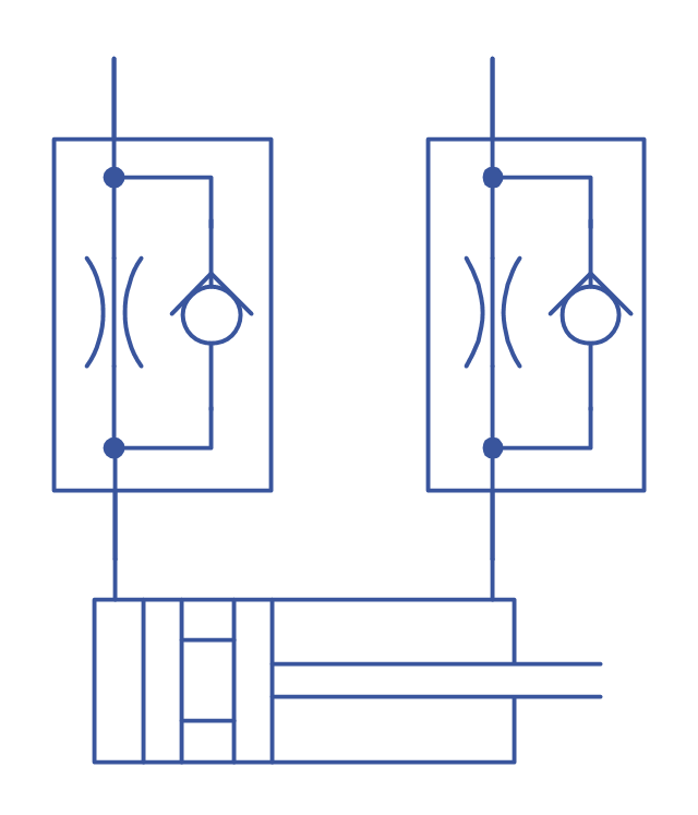
Retract resistor check valve application: pneumatic cylinder, piston driven by Compressed air through 2 Retract resistor check valves.
"A check valve, clack valve, non-return valve or one-way valve is a valve that normally allows fluid (liquid or gas) to flow through it in only one direction.
Check valves are two-port valves, meaning they have two openings in the body, one for fluid to enter and the other for fluid to leave. There are various types of check valves used in a wide variety of applications. Check valves are often part of common household items. Although they are available in a wide range of sizes and costs, check valves generally are very small, simple, or inexpensive. Check valves work automatically and most are not controlled by a person or any external control; accordingly, most do not have any valve handle or stem. The bodies (external shells) of most check valves are made of plastic or metal.
An important concept in check valves is the cracking pressure which is the minimum upstream pressure at which the valve will operate. Typically the check valve is designed for and can therefore be specified for a specific cracking pressure.
Heart valves are essentially inlet and outlet check valves for the heart ventricles, since the ventricles act as pumps." [Check valve. Wikipedia]
This hydraulic schematic example was redrawn using ConceptDraw PRO diagramming and vector drawing software from the Wikimedia Commons file: Retract resistor check valve application.png.
[commons.wikimedia.org/ wiki/ File:Retract_ resistor_ check_ valve_ application.png]
The hydraulic engineering drawing example "Retract resistor check valve application" was created using the ConceptDraw PRO diagramming and vector drawing software extended with the Mechanical Engineering solution from the Engineering area of ConceptDraw Solution Park.
 Computer and Networks Area
The solutions from Computer and Networks Area of ConceptDraw Solution Park collect samples, templates and vector stencils libraries for drawing computer and network diagrams, schemes and technical drawings.
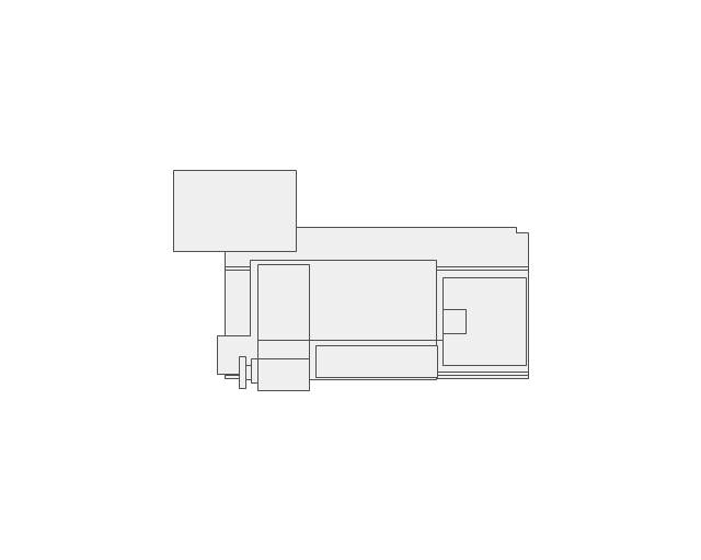
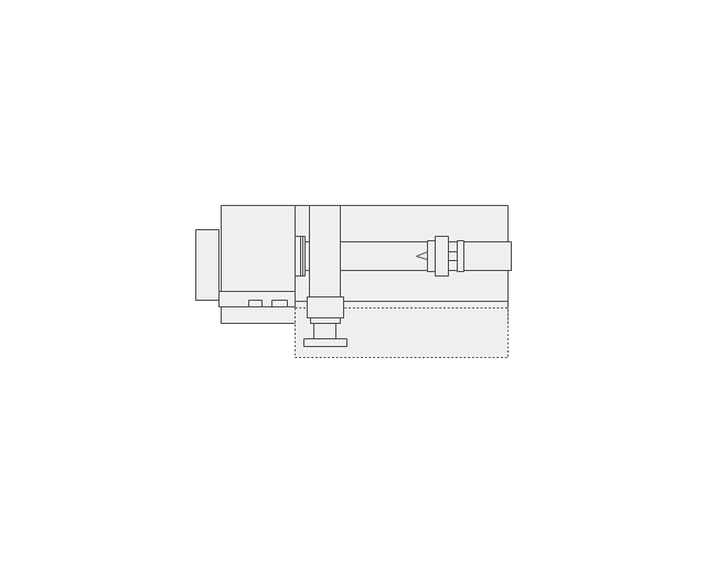
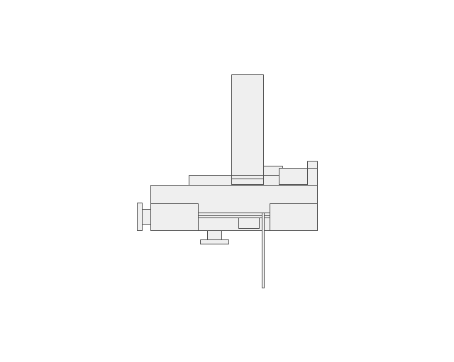
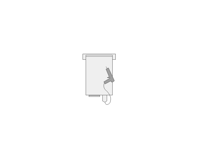
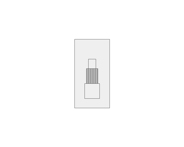
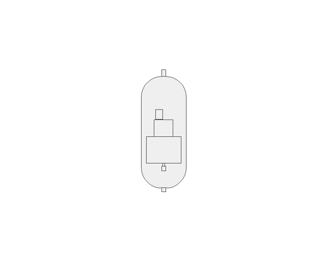
The vector stencils library "Machines and equipment" contains 24 shapes of industrial machines and equipment.
Use it for drawing plant floor plans and manufacturing warehouse layouts the ConceptDraw PRO diagramming and vector drawing software extended with the Plant Layout Plans solution from the Building Plans area of ConceptDraw Solution Park.
www.conceptdraw.com/ solution-park/ building-plant-layout-plans
- Technical drawing - Machine parts assembling | Electrical Drawing ...
- Technical Drawing Software | How to Create a Mechanical Diagram ...
- Basic Flowchart Symbols and Meaning | Technical drawing ...
- Technical drawing - Machine parts assembling | Mechanical ...
- Technical drawing - Machine parts assembling | Process Flowchart ...
- Mechanical Drawing Symbols | Technical Drawing Software ...
- Mechanical Drawing Symbols | Technical drawing - Machine parts ...
- Technical drawing - Machine parts assembling | Flow chart Example ...
- Mechanical Drawing Symbols | Process Flowchart | Technical ...
- Drawing Of Mechanical Steel Parts
- Technical drawing - Machine parts assembling | Total Quality ...
- Technical drawing - Machine parts assembling | Basketball Court ...
- Seven Basic Tools of Quality | Pareto Chart | Technical drawing ...
- Mechanical Drawing Symbols | Engineering | Technical drawing ...
- Technical Drawing Software | Technical drawing - Machine parts ...
- Technical Drawing Software | How to Create a Mechanical Diagram ...
- Mechanical Drawing Symbols | Technical drawing - Machine parts ...
- Mechanical Drawing Symbols | Engineering | UML State Machine ...
- Technical drawing - Machine parts assembling | Machin Drawing ...
- Technical drawing - Machine parts assembling | Techanical Drawing ...

