Swim Lane Diagrams
Swim Lane Diagrams are the kind of process flow diagrams and effective tool for documenting the business processes required for any business company for its productive work, for easy defining the weak points, reasons of defects, or delays during the process. Swim Lane Diagram is based on the IDEF3 standard and was developed primarily for using in projecting. Its name derives from the use of horizontal or vertical lanes. The blocks that denote the parts of the processes are arranged within definite lanes according to the belonging to responsible worker. So the process of any complexity is visually divided into the parts and represented with indication the responsibility for execution of each part. This significantly facilitates the comprehension of its work. Use the ConceptDraw DIAGRAM software and predesigned vector objects from the Swim Lanes library of Business Process Mapping Solution included to ConceptDraw Solution Park to easy develop Swim Lanes Flowcharts and Diagrams, for modeling and documenting the business processes in a simple and visual graphic form.IDEF1X Standard
Use Case Diagrams technology. IDEF1x standard - for work with relational data bases. IDEF1x standard is meant for constructing of conceptual schemes which represent the structure of data in the context of the concerned system, for example, a commercial organization.Express-G Diagram
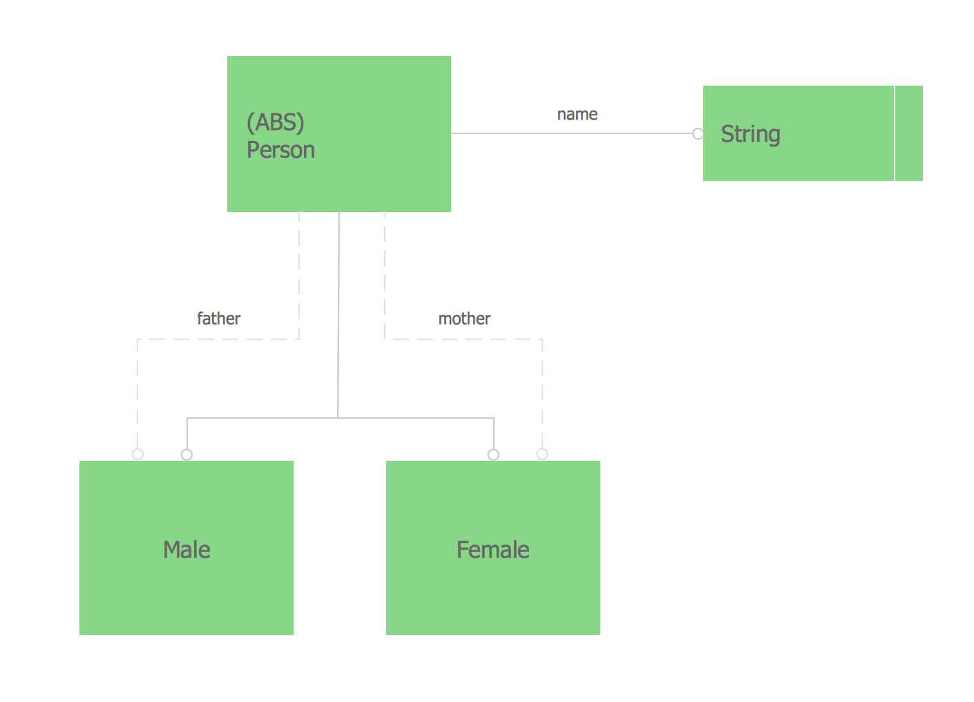
The vector stencils library from the solution Information Model Diagrams contains specific data type symbols of the EXPRESS-G notation such as entity data type symbols, simple data type symbols, enumeration data type symbols, defined data type symbols, select data type symbols and specific attribute symbols for ConceptDraw DIAGRAM diagramming and vector drawing software. The Information Model Diagrams solution is contained in the Software Development area of ConceptDraw Solution Park.Databases Access Objects Model with ConceptDraw DIAGRAM
ConceptDraw Basic gives the opportunity of interaction with any ODBC-compatible databases. For this the Database Access Objects Model is provided. All calls to the database are made by certain methods of objects of this model.
 Wireless Networks
The Wireless Networks Solution extends ConceptDraw DIAGRAM software with professional diagramming tools, set of wireless network diagram templates and samples, comprehensive library of wireless communications and WLAN objects to help network engineers and designers efficiently design and create Wireless network diagrams that illustrate wireless networks of any speed and complexity, and help to identify all required equipment for construction and updating wireless networks, and calculating their costs.
- Er Diagram For Traffic Management System
- Class Diagram For Agriculture Management System
- UML Class Diagram Example for Transport System
- Class Diagram For Traffic Management System
- Dfd Diagram For Traffic Management System
- Agriculture Management Er Diagram
- Traffic Management System Data Flow Diagram
- Entity-Relationship Diagram (ERD) with ConceptDraw PRO | UML ...
- Entity Relationship Diagram Software Engineering | Campus Area ...
- Building Drawing Software for Design Site Plan | UML Diagram of ...
- UML Diagram of Parking | UML Activity Diagram | Inter-vehicle ...
- Entity-Relationship Diagram (ERD) with ConceptDraw PRO ...
- Interaction Overview Diagram | Venn Diagram Examples for ...
- How To Make Chen ER Diagram | Process Flowchart | Entity ...
- UML Class Diagram Example for Transport System
- Data Flow Diagram Of Traffic Management System
- Flow Chart Diagram On Farm Management System
- Process Flowchart | Design elements - UML class diagrams ...
- Data Flow Diagram For A Farm Management System
- Example Of Activity Diagram Of Supermarket


