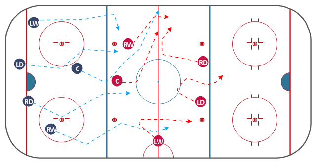
"The neutral zone trap (often referred to as simply the trap) is a defensive strategy used in ice hockey to prevent an opposing team from proceeding through the neutral zone (the area between the blue lines) to force turnovers. The strategy is generally used to level the playing field for teams that are not as offensively talented as their opponents, although the trap can also be used by teams simply looking to protect a lead late in the game. The trap was innovated by the Toronto Maple Leafs in the 1920s and 1930s, and more recently in the mid to late 1990s and early 2000s by the New Jersey Devils." [Neutral zone trap. Wikipedia]
The diagram example "Ice hockey - Defensive strategy - Neutral zone trap" was created using the ConceptDraw PRO diagramming and vector drawing software extended with the Hockey solution from the Sport area of ConceptDraw Solution Park.
The diagram example "Ice hockey - Defensive strategy - Neutral zone trap" was created using the ConceptDraw PRO diagramming and vector drawing software extended with the Hockey solution from the Sport area of ConceptDraw Solution Park.
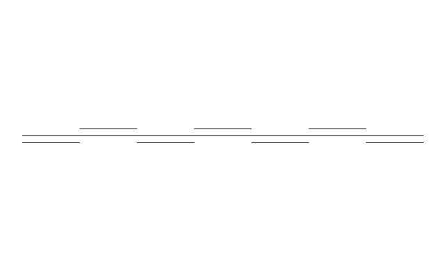
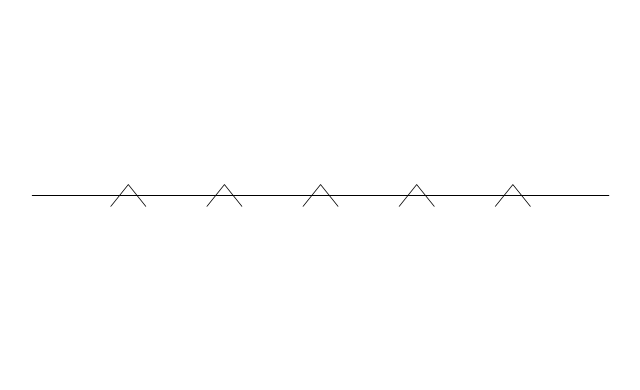
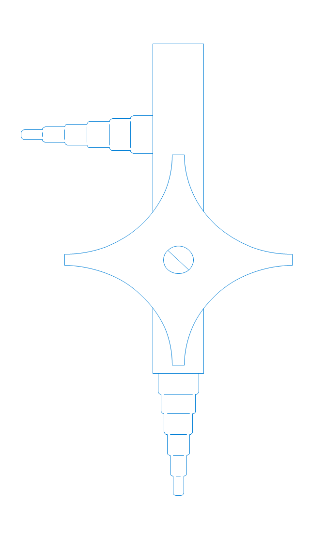
The vector stencils library "Pipes 2" contains 48 symbols of pipes. Use it for drawing plumbing and piping building plans, schematic diagrams, blueprints, or technical drawings of waste water disposal systems, hot and cold water supply systems in the ConceptDraw PRO diagramming and vector drawing software extended with the Plumbing and Piping Plans solution from the Building Plans area of ConceptDraw Solution Park.
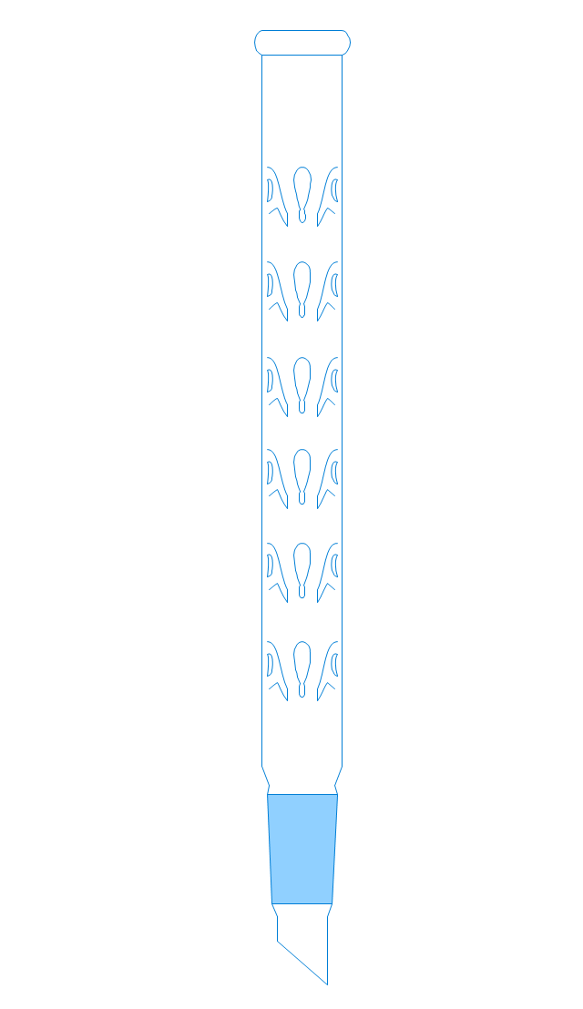
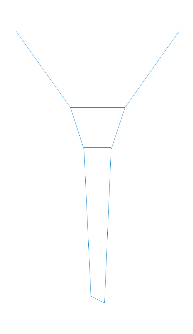
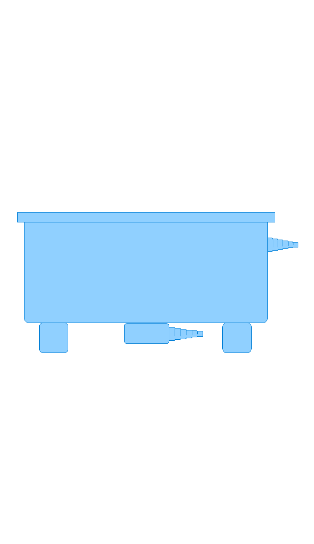
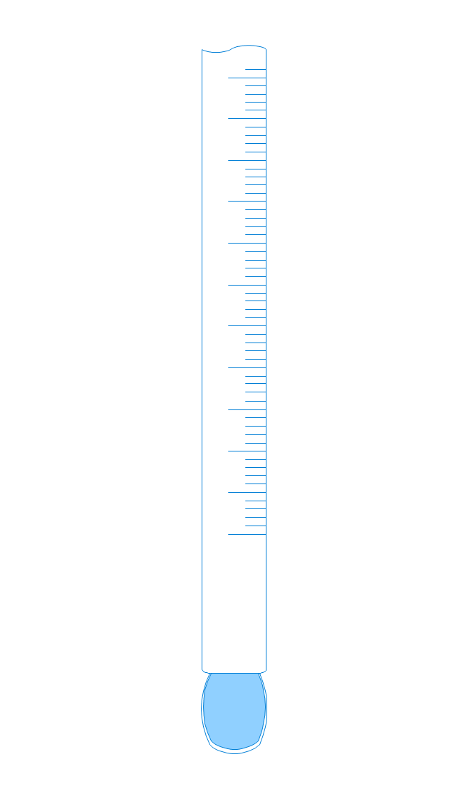
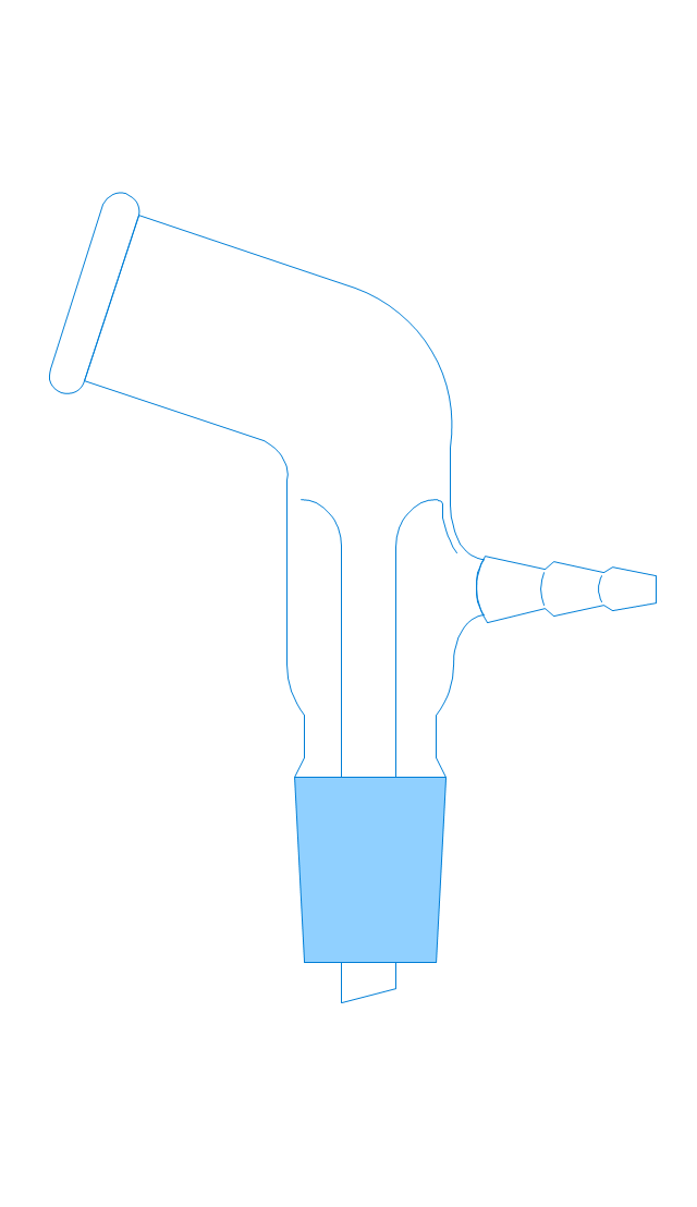
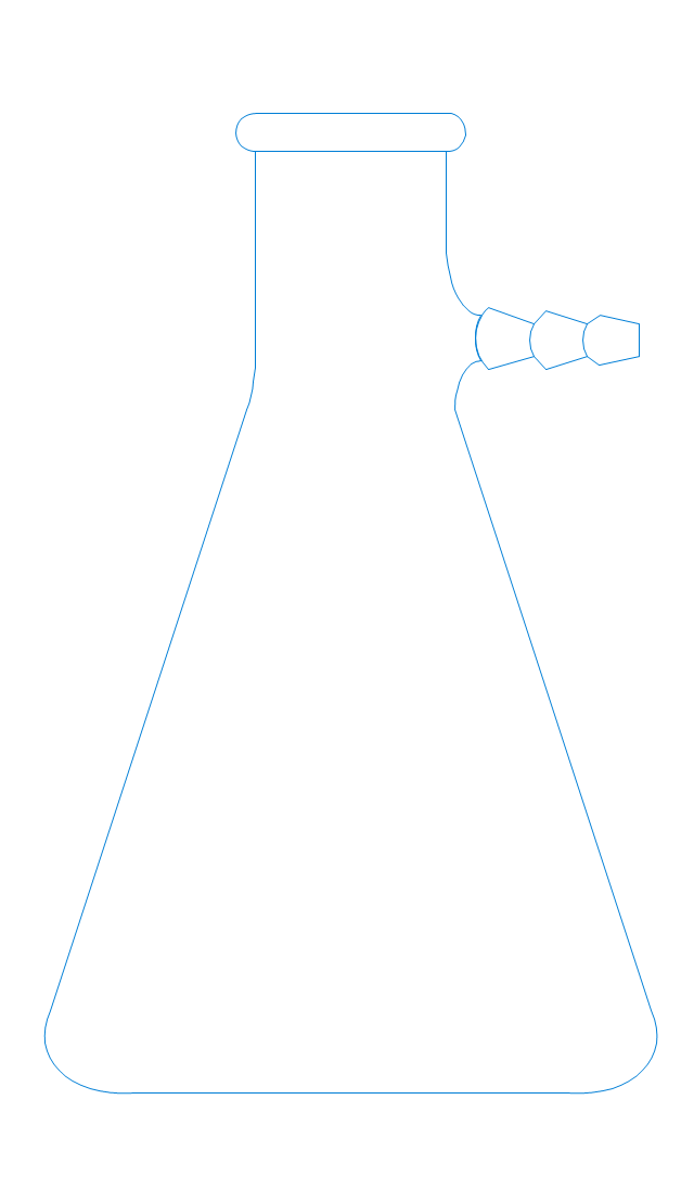
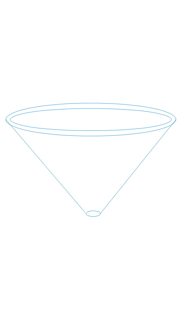
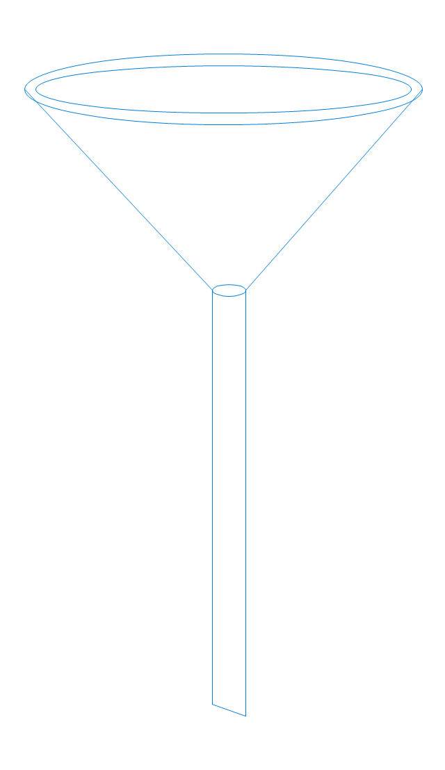
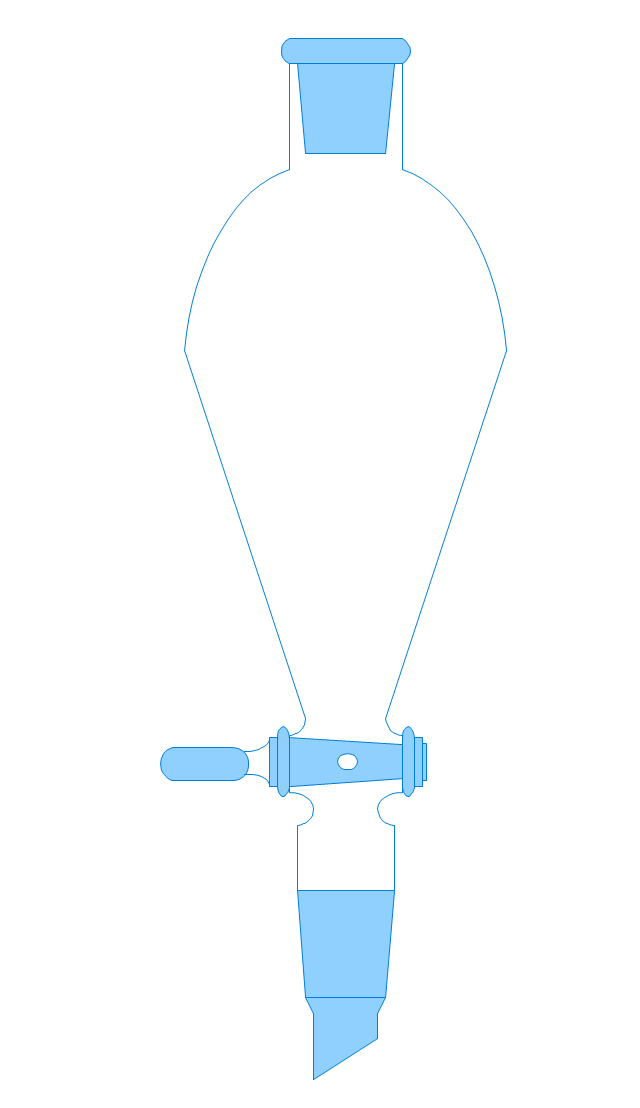
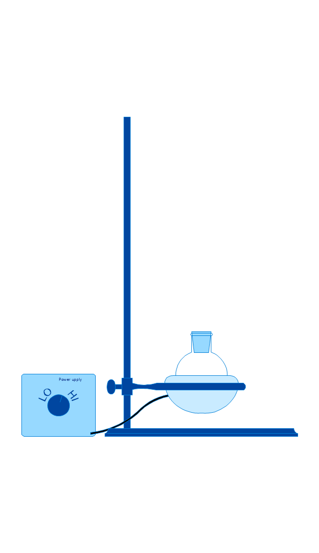
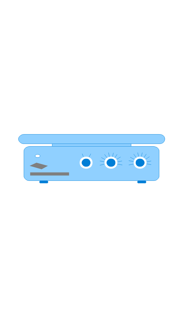
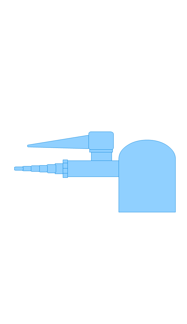
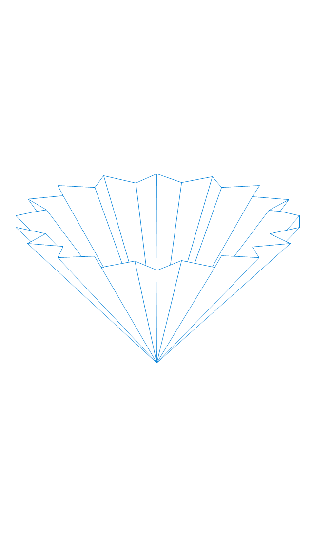
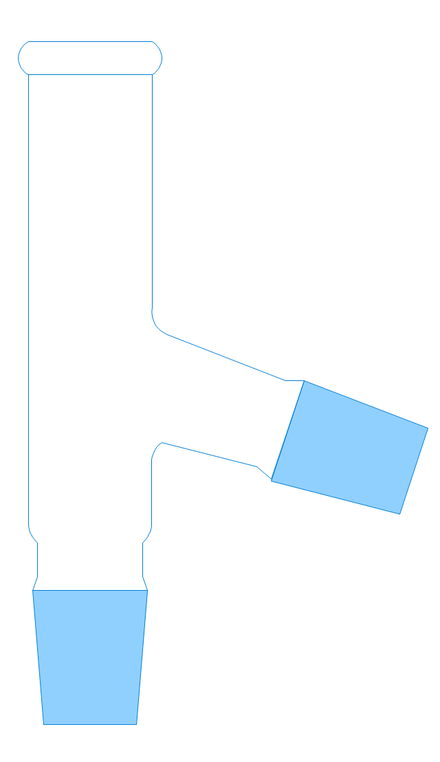
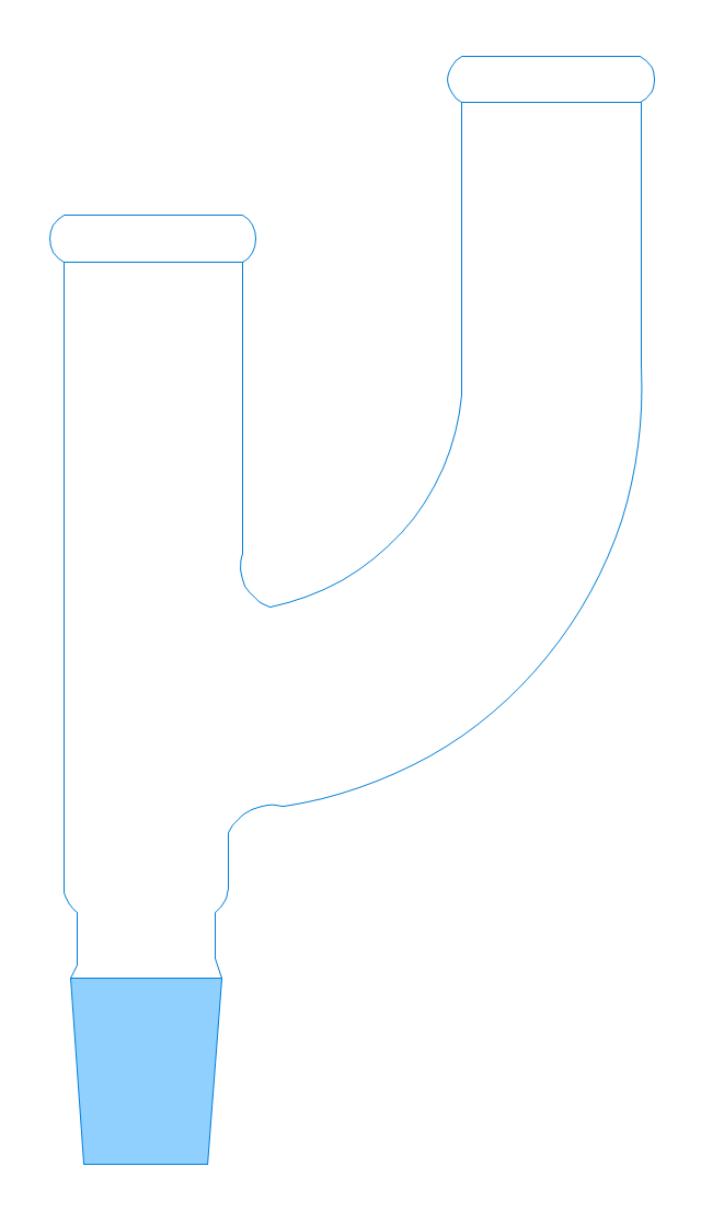
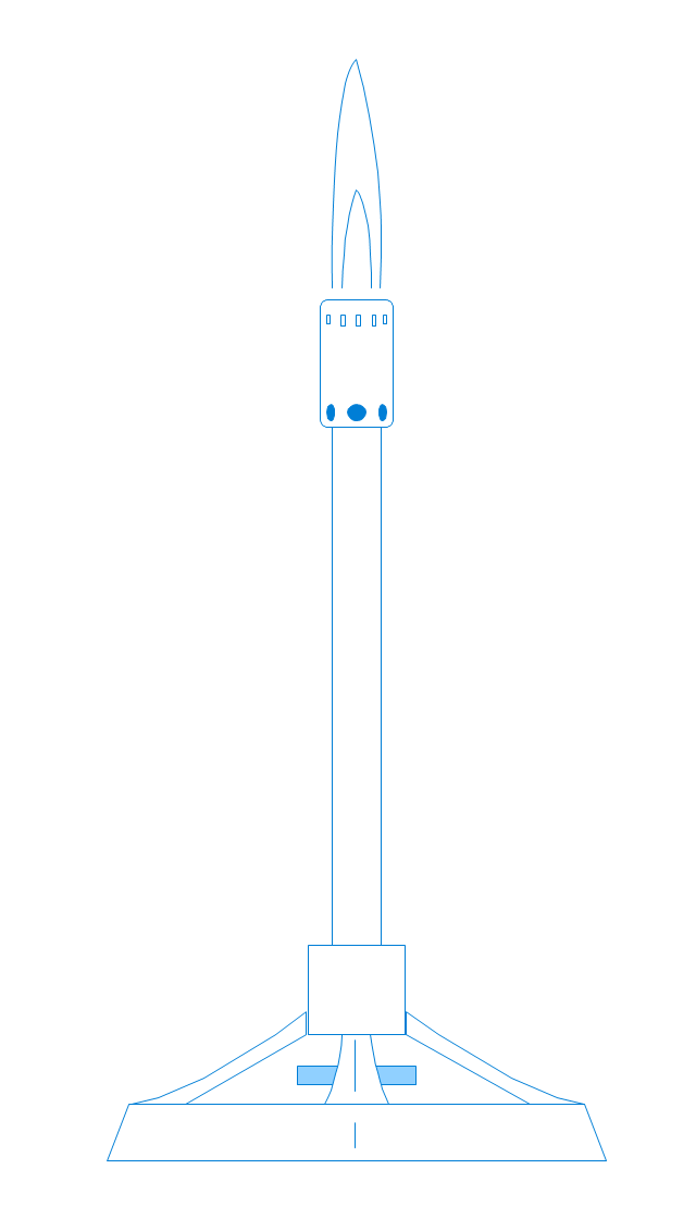
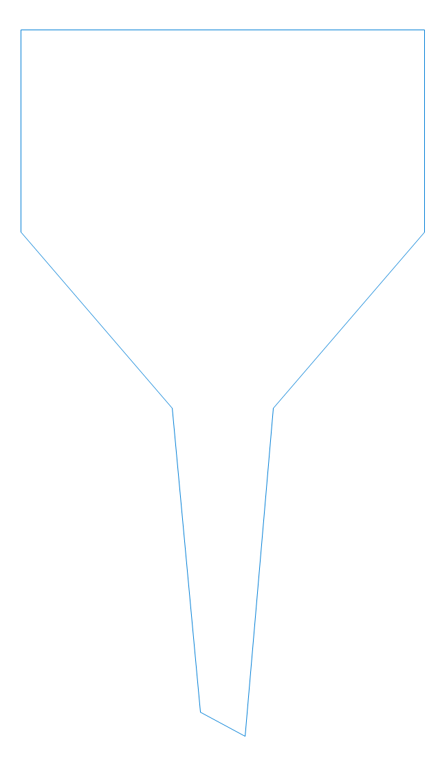
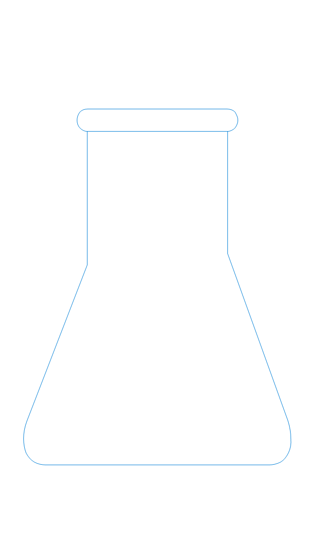
The vector stencils library "Laboratory equipment" contains 31 clipart icons of chemical laboratory equipment and labware.
Use these shapes for drawing part assembly and mounting schemes of glassware apparatus in chemical experiment diagrams and illustrations in the ConceptDraw PRO diagramming and vector drawing software extended with the Chemistry solution from the Science and Education area of ConceptDraw Solution Park.
Use these shapes for drawing part assembly and mounting schemes of glassware apparatus in chemical experiment diagrams and illustrations in the ConceptDraw PRO diagramming and vector drawing software extended with the Chemistry solution from the Science and Education area of ConceptDraw Solution Park.
 Ice Hockey
The Ice Hockey Solution extends the capabilities of ConceptDraw PRO v9.5 (or later) with samples, templates, and libraries of vector objects for drawing hockey diagrams, plays schemas, and illustrations. The Ice Hockey Solution can be used to make polishe
The vector stencils libraries "Pipes 1" and "Pipes 2" contain 28 and 48 pipe, tubing and fitting symbols, respectively.
"Pipe is hollow cylinder used to conduct or transfer fluids (liquids and gases) from one place to other place. The main difference between pipe and tube is the critical dimension used to describe the pipe size or the tube size. For pipe, internal diameter (ID) roughly corresponds to the nominal pipe size for standard wall thickness. For tube, the outer diameter (OD) closely corresponds to the tube size. In current European standards pipes and tubes are nowadays described as outside diameter by wall thickness. The three standard types of pipe ends used in the piping industriesare; Plain Ends (PE), Threaded Ends (TE) and Beveled Ends (BE). In the past, many types of material have been used in conveying water from one point to another. Masonry and wood were probably the first materials used. Plastics are the newest, and are now being used quite extensively." [Piping. Wikipedia]
Use the design elements libraries "Pipes 1" and "Pipes 2" for drawing plumbing and piping building plans, schematic diagrams, blueprints, or technical drawings of waste water disposal systems, hot and cold water supply systems using the ConceptDraw PRO diagramming and vector drawing software.
The shapes libraries "Pipes 1" and "Pipes 2" are contained in the Plumbing and Piping Plans solution from the Building Plans area of ConceptDraw Solution Park.
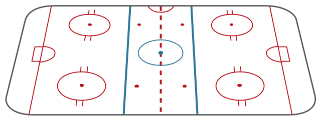
"Markings.
Lines.
The centre line divides the ice in half crosswise. It is used to judge icing, meaning that if a team sends the puck across the centre line (red line), blue line and then across the goal line (that is to say, shoots or dumps the puck past the goal line from behind their own side of the centre line) it is said to be icing. ...
Faceoff spots and circles.
There are 9 faceoff spots on a hockey rink. Most faceoffs take place at these spots. There are two spots in each end zone, two at each end of the neutral zone, and one in the centre of the rink.
There are faceoff circles around the centre ice and end zone faceoff spots. There are hash marks painted on the ice near the end zone faceoff spots. The circles and hash marks show where players may legally position themselves during a faceoff or in game play. ...
Spot and circle dimensions.
Both the center faceoff spot and center faceoff circle are blue. The spot is a solid blue circle 12 inches (30 cm) in diameter. Within the spot is a center, a circle 30 feet (9.1 m) in diameter, painted with a blue line 2 inches (5.1 cm) in width.
All of the other faceoff spots have outlines 2 inches (5.1 cm) thick, forming a circle 2 feet (0.61 m) in diameter measured from the outsides of the outlines, and are filled in with red in all areas except for the 3 inches (7.6 cm) space from the tops and bottoms of the circles, measured from the insides of the outline. ...
Goal posts and nets.
At each end of the ice, there is a goal consisting of a metal goal frame and cloth net in which each team must place the puck to earn points. According to NHL and IIHF rules, the entire puck must cross the entire goal line in order to be counted as a goal. ...
Goal area.
The crease is a special area of the ice designed to allow the goaltender to perform without interference. In most leagues, goals are disallowed if an attacking player enters the goal crease with a stick, skate, or any body part before the puck. For the purposes of this rule, the crease extends vertically from the painted lines to the top of the goal frame. ...
Goaltender trapezoid.
During the 2004-05 American Hockey League (AHL) season, an experimental rule was implemented for the first seven weeks of the season, instituting a goaltender trap zone, more commonly called the trapezoid in reference to its shape. Under the rule, it is prohibited for the goaltender to handle the puck anywhere behind the goal line that is not within the trapezoidal area. If they do so they are assessed a minor penalty for delay of game. ...
Referee's crease.
The referee's crease is a semicircle ten feet in radius in front of the scorekeepers bench." [Ice hockey rink. Wikipedia]
The diagram template "Ice hockey rink view from long side" for the ConceptDraw PRO diagramming and vector drawing software is included in the Hockey solution from the Sport area of ConceptDraw Solution Park.
"Offensive tactics in set pieces. ...
Throw-ins[edit]
How throw-ins are best handled depends on where it is:
(1) In one's own half the aim of a throw-in may be to retain possession in order to build up the next attack. The throw may or may not go toward the opponents' goal; the most unmarked player may be a full-back who is behind the ball. Such a throw followed by a quickly taken 'switch' pass can be an effective tactic. Under pressure however, the ball is often thrown up the line, toward the opponents' goal line to gain as much ground as possible.
(2) If the thrower is unmarked, a simple tactic is to take a short throw to the feet or chest of a marked player who immediately returns the ball to the thrower.
(3) In the last third of the pitch a player with a long throw can put pressure onto the defenders by throwing the ball deep into the opponents' penalty area, resulting in somewhat similar tactics to a corner kick situation, but with the added advantage of avoiding the offside trap, as an attacking player cannot be offside from a throw in. ...
Goal kicks.
A goal kick is an important 'set piece' that will occur many times in a game and yet few teams practice it. If taken quickly the kick may be taken short to a full-back who has run into a wide position. Although this may gain little ground it retains the all-important possession of the ball. A longer kick to the midfield is more common and it is vital that the midfield unit are in a position to receive it.
Corners.
A corner kick (or "corner") is a real goal scoring opportunity and it is essential to know who is the best at taking a good corner from both the left and right side of the pitch. A good corner will be aimed high across the goal and may be 'bent' towards or away from the goal. At least one of the forwards should be on or close to the goal line when the kick is taken.
Another tactic on a corner is to let the best shooter stay in the back "trash" position and have the defence worried about those up front. The player taking the corner kick makes a small pass back to the trash shooter who has time and space to take a good shot." [Association football tactics and skills. Wikipedia]
The diagram example "Association football (soccer) - The pitch: throw-ins, goal kicks, corners" was created using the ConceptDraw PRO diagramming and vector drawing software extended with the Football solution from the Sport area of ConceptDraw Solution Park.
www.conceptdraw.com/ solution-park/ sport-soccer
The vector stencils libraries "Pipes 1" and "Pipes 2" contain 28 and 48 pipe, tubing and fitting symbols, respectively.
"Pipe is hollow cylinder used to conduct or transfer fluids (liquids and gases) from one place to other place. The main difference between pipe and tube is the critical dimension used to describe the pipe size or the tube size. For pipe, internal diameter (ID) roughly corresponds to the nominal pipe size for standard wall thickness. For tube, the outer diameter (OD) closely corresponds to the tube size. In current European standards pipes and tubes are nowadays described as outside diameter by wall thickness. The three standard types of pipe ends used in the piping industriesare; Plain Ends (PE), Threaded Ends (TE) and Beveled Ends (BE). In the past, many types of material have been used in conveying water from one point to another. Masonry and wood were probably the first materials used. Plastics are the newest, and are now being used quite extensively." [Piping. Wikipedia]
Use the design elements libraries "Pipes 1" and "Pipes 2" for drawing plumbing and piping building plans, schematic diagrams, blueprints, or technical drawings of waste water disposal systems, hot and cold water supply systems using the ConceptDraw PRO diagramming and vector drawing software.
The shapes libraries "Pipes 1" and "Pipes 2" are contained in the Plumbing and Piping Plans solution from the Building Plans area of ConceptDraw Solution Park.
"Pipe is hollow cylinder used to conduct or transfer fluids (liquids and gases) from one place to other place. The main difference between pipe and tube is the critical dimension used to describe the pipe size or the tube size. For pipe, internal diameter (ID) roughly corresponds to the nominal pipe size for standard wall thickness. For tube, the outer diameter (OD) closely corresponds to the tube size. In current European standards pipes and tubes are nowadays described as outside diameter by wall thickness. The three standard types of pipe ends used in the piping industriesare; Plain Ends (PE), Threaded Ends (TE) and Beveled Ends (BE). In the past, many types of material have been used in conveying water from one point to another. Masonry and wood were probably the first materials used. Plastics are the newest, and are now being used quite extensively." [Piping. Wikipedia]
Use the design elements libraries "Pipes 1" and "Pipes 2" for drawing plumbing and piping building plans, schematic diagrams, blueprints, or technical drawings of waste water disposal systems, hot and cold water supply systems using the ConceptDraw PRO diagramming and vector drawing software.
The shapes libraries "Pipes 1" and "Pipes 2" are contained in the Plumbing and Piping Plans solution from the Building Plans area of ConceptDraw Solution Park.
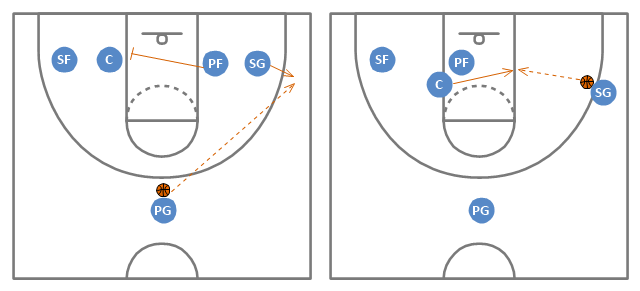
"The various types of offenses are designed to use teamwork to free up or isolate players for good shots against a multitude of defenses. Offenses must be simple with the emphasis on execution and fundamentals. Offensive spacing should provide for strong offensive rebounding position as well as allowing for defensive balance. Offenses must be flexible to meet various types of defensive pressure. They must also have counter options that take advantage of any defensive overplays and traps. Offenses can be categorized into Early, Set, Motion, Zone, and Spread." [hooptactics.com/ Basketball_ Basics_ Offenses]
The basketball positions diagram example "Basketball plays - 1-4 low stack offense" was created using the ConceptDraw PRO diagramming and vector drawing software extended with the Basketball solution from the Sport area of ConceptDraw Solution Park.
www.conceptdraw.com/ solution-park/ sport-basketball
- Ice Hockey Diagram – Defensive Strategy – Neutral Zone Trap | Ice ...
- Ice Hockey Diagram – Defensive Strategy – Neutral Zone Trap | Ice ...
- Ice hockey - Defensive strategy - Neutral zone trap
- Successful Strategic Plan | Ice Hockey Diagram – Defensive ...
- Social strategy - Pyramid diagram | Ice Hockey Diagram – Defensive ...
- Ice Hockey Diagram – Penalty Kill Forecheck Angling Drill | Ice ...
- Laboratory equipment - Vector stencils library
- Ice Hockey Diagram – Entering Offensive Zone Drill | Ice Hockey ...
- Ice Hockey Positions Diagram
- Defensive Strategy Diagram – 46 Defence | Ice Hockey Diagram ...
- Ice Hockey Rink Dimensions | Ice Hockey Diagram – Entering ...
- Defensive Strategy Diagram – 46 Defence | Offensive Strategy ...
- Design elements - Pipes (part 2)
- Interior Design Piping Plan - Design Elements | Pipes 2 - Vector ...
- Ice Hockey Diagram – Entering Offensive Zone Drill | Baseball ...
- Ice Hockey Rink Dimensions
- Ice Hockey Rink Diagram
- Ice Hockey Positions Diagram | Ice Hockey Rink Dimensions | Ice ...
- Reducer
- Design elements - Pipes (part 2)

--laboratory-equipment---vector-stencils-library.png--diagram-flowchart-example.png)
-laboratory-equipment---vector-stencils-library.png--diagram-flowchart-example.png)
-laboratory-equipment---vector-stencils-library.png--diagram-flowchart-example.png)


.png--diagram-flowchart-example.png)
-tactics-diagram-association-football-(soccer)---the-pitch:-throw-ins,-goal-kicks,-corners.png--diagram-flowchart-example.png)
