Export from ConceptDraw PRO Document to a Graphic File
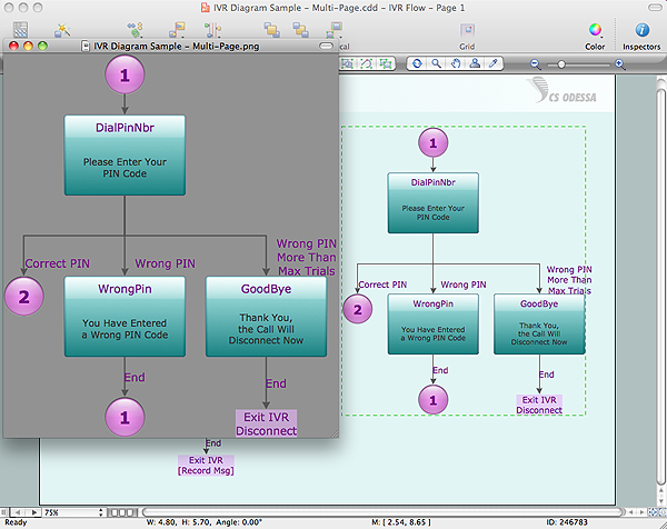
Now it’s easy to share your visual documents with other people in a form most convenient for them. ConceptDraw PRO can save your drawings and diagrams in a number of highly useful formats, including graphic files. You can save your drawing as a .PNG, .JPG, or other graphic format file.
Building Networks
The ConceptDraw PRO is a best Network Diagramming software.How To use House Electrical Plan Software
How we can conduct the electricity at house correctly without a plan? It is impossible. The House electrical diagram depicts locations of switches, outlets, dimmers and lights, and lets understand how you will connect them. But design of House Electrical Plan looks a complex task at a glance, which requires a lot of tools and special experience. But now all is simple with all-inclusive floor plan software - ConceptDraw PRO. As a house electrical plan software, the ConceptDraw PRO contains libraries with a large range of professional lighting and electrical symbols, ready-to-use electrical plans samples and examples, and built-in templates for creating great-looking Home floor electrical plans. It is a fastest way to draw Electrical circuit diagrams, Electrical wiring and Circuit schematics, Digital circuits, Electrical equipment, House electrical plans, Satellite television, Cable television, Home cinema, Closed-circuit television when are used the tools of Electric and Telecom Plans Solution from ConceptDraw Solution Park. Files created in Visio for Mac app can be easily imported to ConceptDraw PRO. Also you may import stencils and even libraries. Try for free an alternative to Visio that Apple users recommend.
Emergency Plan
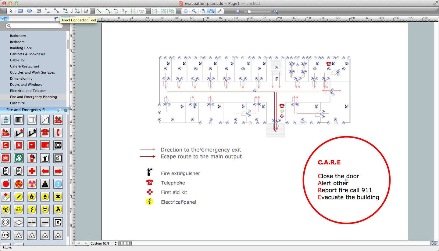
The Fire Emergency Plan illustrates the scheme of the building and location of the main and fire exits for a safe evacuation, and clearly defines directions to them on the plan. Fire Emergency Plans are constructed on the case of unexpected or emergency situations, fires, hazardous leaks, natural disasters, and other sudden events. They must to be obligatorily on the plain sight at every building and on each floor, at living houses and apartments, schools and universities, medical centers, clinics and hospitals, office buildings, banks, cafes, restaurants, and also at all other public buildings and institutions. The Evacuation plans and Emergency Plans preliminary designed in ConceptDraw PRO software help employees and family members when some emergency events happen and let avoid the accidents and sad consequences, prevent injuries and fatalities, allow reduce damages and speed the work resumption. Start drawing emergency blueprint from floor bounds, then add the inner walls and doors, and finally use bright arrows to visually show evacuation directions to fire exits. ConceptDraw is a serious alternative to Visio. It's a desktop based solution aimed at professional designers working in CAD environments. It is also a good option for those who work between Mac and PC because one license is valid for both.
Flow Chart Symbols
The Flowcharts are incredibly useful and popular tool used in science, business, software development, analytics, engineering, marketing, manufacturing, administration, architecture, government, politics, and many other fields thanks to a variety of existing types of flowcharts. A Flowchart is a visual graphical representation of the process, algorithm, or the set of steps taken for problem's solution. Widely used for designing, visualizing and documenting simple and complex processes and programs, they effectively help to understand the process and to find easier the flaws if they are. Each flowchart type supposes the use of its own set of notations for drawing corresponding diagram, which includes the symbols of process, decision, data, document, data base, termination, initiation processes, processing loops, conditions, etc. It is easily design a Flowchart using the special professional flowchart maker - ConceptDraw PRO diagram software with numerous predesigned flow chart symbols grouped in libraries of Flowcharts solution from ConceptDraw Solution Park."Surround sound is a technique for enriching the sound reproduction quality of an audio source with additional audio channels from speakers that surround the listener (surround channels), providing sound from a 360° radius in the horizontal plane (2D) as opposed to "screen channels" (centre, [front] left, and [front] right) originating only from the listener's forward arc.
Surround sound is characterized by a listener location or sweet spot where the audio effects work best, and presents a fixed or forward perspective of the sound field to the listener at this location. The technique enhances the perception of sound spatialization by exploiting sound localization; a listener's ability to identify the location or origin of a detected sound in direction and distance. Typically this is achieved by using multiple discrete audio channels routed to an array of loudspeakers.
There are various surround sound based formats and techniques, varying in reproduction and recording methods along with the number and positioning of additional channels." [Surround sound. Wikipedia]
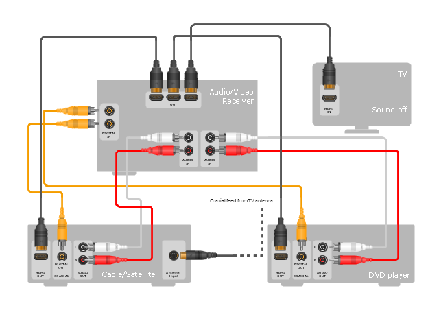
The hookup diagram example "Hook up drawing - Home entertainment system with surround sound" was created using the ConceptDraw PRO diagramming and vector drawing software extended with the Audio and Video Connectors solution from the Engineering area of ConceptDraw Solution Park.
Metropolitan area networks (MAN). Computer and Network Examples
A Metropolitan Area Network (MAN) is a great computer network located on the large geographical area or region. It is a network bigger than Local Area Network (LAN), but territorially smaller than Wide Area Network (WAN), its diameter usually ranges from 5 to 50 kilometers. MAN usually includes several buildings or even the whole city (metropolis). It is based on high data rate compounds using the fiber channels and other digital data transmission channels. MAN includes a lot of communicating devices, for its construction are used multiple routers, switches and hubs. MAN can combine together several Local Area Networks or Campus Area Networks located in different buildings within a city and provides the Internet connectivity for them. Solutions included to Computer and Networks Area for ConceptDraw Solution Park are the real godsend for those who want design Computer Network Diagrams, and among others the Metropolitan Area Network Diagrams. They offer the libraries with ready-to-use vector design elements, professional-looking examples, samples and templates.
Television networks. Computer and Network Examples
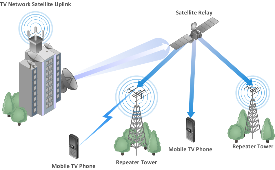
A Television network is a telecommunications network that allows to distribute the television program content. The central operation provides programming to the many television stations or pay TV providers. This example was created in ConceptDraw PRO using the Computer and Networks Area of ConceptDraw Solution Park and shows the TV broadcasting mechanism and TV network service.
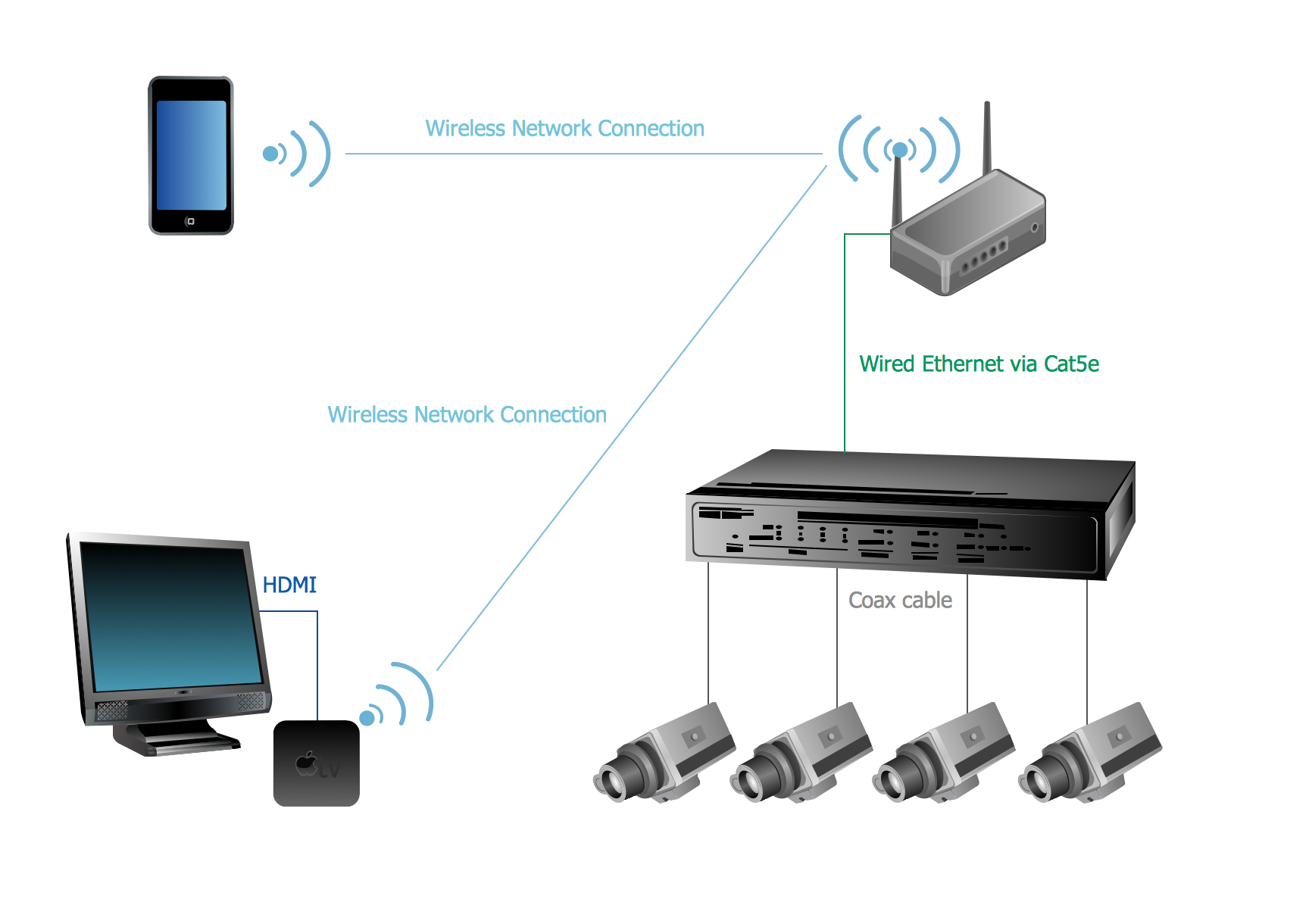
CCTV Network Example
The following examples cctv network were created in ConceptDraw PRO diagramming and vector drawing software using the Audio, Video, Media Solution. Using this easily customizable cctv network template you can represent any existing cctv network.- Export from ConceptDraw PRO Document to a Graphic File | TV ...
- Audio and Video Connectors | TV , Photo and Video - Vector stencils ...
- Cable TV - Vector stencils library | IVR Internet - Vector stencils ...
- TV , Photo and Video - Vector stencils library | Interior Design Office ...
- TV , Photo and Video - Vector stencils library | Professions - Vector ...
- Mobile satellite TV network diagram | Design elements - Cable TV ...
- TV , Photo and Video - Vector stencils library | Design elements - TV ...
- TV , Photo and Video - Vector stencils library | TV , Photo and Video ...
- Camera Png
- TV , Photo and Video - Vector stencils library | Office equipment ...
