HelpDesk
How to Connect Objects on PC
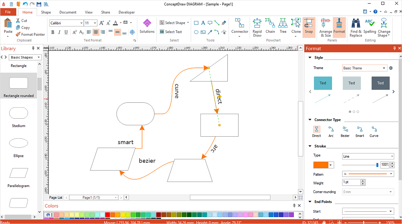
ConceptDraw DIAGRAM provides a few options for drawing connections between objects: Direct Connectors, Smart, Arc, Bezier, Curve and Round Connectors. You can connect objects in your ConceptDraw diagram with proper connectors using the embedded automatic connection modes. This article describes how you can connect objects with connectors and how you can ascribe different types and behaviors.IDEF3 Standard
Use Case Diagrams technology. IDEF3 Standard is intended for description and further analysis of technological processes of an enterprise. Using IDEF3 standard it is possible to examine and model scenarios of technological processes.HelpDesk
How to Connect Objects on Mac
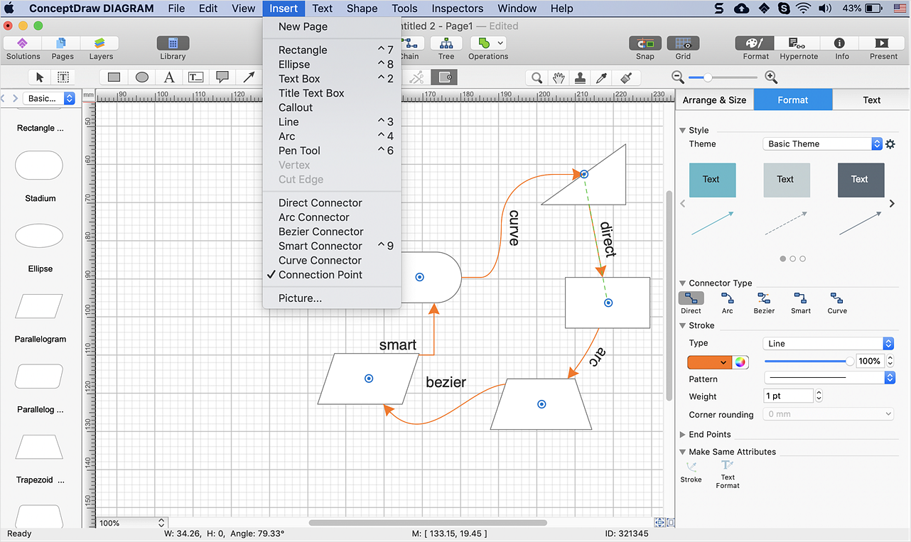
ConceptDraw DIAGRAM provides a few options for drawing connections between. This article describes how you can connect objects with connectors and how you can ascribe them different types and behaviors.ConceptDraw Arrows10 Technology
You want to connecting objects manually? You don't know how should diagramming software work? Is it possible to develop a diagram as quickly as the ideas come to you? Yes. The innovative ConceptDraw Arrows10 Technology - This is more than enough versatility to draw any type of diagram with any degree of complexity. You can start draw your diagram manually now.
 Mechanical Engineering
This solution extends ConceptDraw DIAGRAM.9 mechanical drawing software (or later) with samples of mechanical drawing symbols, templates and libraries of design elements, for help when drafting mechanical engineering drawings, or parts, assembly, pneumatic,
Data structure diagram with ConceptDraw DIAGRAM
Data structure diagram (DSD) is intended for description of conceptual models of data (concepts and connections between them) in the graphic format for more obviousness. Data structure diagram includes entities description, connections between them and obligatory conditions and requirements which connect them. Create Data structure diagram with ConceptDraw DIAGRAM.Bubble diagrams in Landscape Design with ConceptDraw DIAGRAM
Bubble Diagrams are the charts with a bubble presentation of data with obligatory consideration of bubble's sizes. They are analogs of Mind Maps and find their application at many fields, and even in landscape design. At this case the bubbles are applied to illustrate the arrangement of different areas of future landscape design, such as lawns, flowerbeds, playgrounds, pools, recreation areas, etc. Bubble Diagram helps to see instantly the whole project, it is easy for design and quite informative, in most cases it reflects all needed information. Often Bubble Diagram is used as a draft for the future landscape project, on the first stage of its design, and in case of approval of chosen design concept is created advanced detailed landscape plan with specification of plants and used materials. Creation of Bubble Diagrams for landscape in ConceptDraw DIAGRAM software is an easy task thanks to the Bubble Diagrams solution from "Diagrams" area. You can use the ready scanned location plan as the base or create it easy using the special ConceptDraw libraries and templates.- Welded joints types | Butt weld geometry | Elements location of a ...
- Elements location of a welding symbol | Mechanical Engineering ...
- Mechanical Drawing Symbols | Mechanical Engineering ...
- Types of Flowcharts | Drawing Activity On Arc Network Arrow ...
- About Welded Joint In Engineering Drawing
- Lap Joint Types Engineering Drawing
- Types of Welding in Flowchart | Elements location of a welding ...
- Butt weld geometry | Welded joints types | Design elements ...
- Butt weld geometry | Welded joints types | Welding - Vector stencils ...
- Engineering Drawing In Welding
- Joints Engineering Drawing
- Butt weld geometry | Welded joints types | Elements location of a ...
- Welding symbols | Elements location of a welding symbol | Design ...
- Elements location of a welding symbol | Types of Welding in ...
- Welded Joint Diagram
- Types of Welding in Flowchart | Entity Relationship Diagram ...
- Technical drawing - Machine parts assembling | Mechanical ...
- Drawing Of Butt Joint In Welding
- Process Flowchart | Types of Flowcharts | Chemical Engineering ...
- Wikipedia Engineering Drawing


