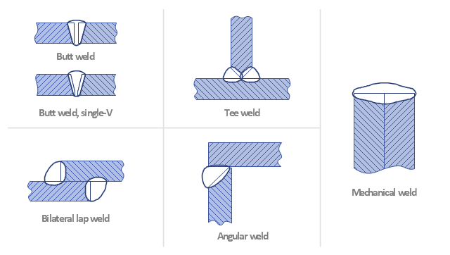
Types of Welding in Flowchart

This engineering drawing shows different types of geometry of butt welds.
"Welds can be geometrically prepared in many different ways. The five basic types of weld joints are the butt joint, lap joint, corner joint, edge joint, and T-joint (a variant of this last is the cruciform joint). Other variations exist as well - for example, double-V preparation joints are characterized by the two pieces of material each tapering to a single center point at one-half their height. Single-U and double-U preparation joints are also fairly common - instead of having straight edges like the single-V and double-V preparation joints, they are curved, forming the shape of a U. Lap joints are also commonly more than two pieces thick - depending on the process used and the thickness of the material, many pieces can be welded together in a lap joint geometry." [Welding. Wikipedia]
This engineering drawing example was redesigned using the ConceptDraw PRO diagramming and vector drawing software from the Wikimedia Commons file: Butt Weld Geometry.GIF.
[commons.wikimedia.org/ wiki/ File:Butt_ Weld_ Geometry.GIF]
The engineering drawing example "Butt weld geometry" is included in the Mechanical Engineering solution from the Engineering area of ConceptDraw Solution Park.
Welding joint diagram

IDEF9 Standard

"A welding joint is a point or edge where two or more pieces of metal or plastic are joined together. They are formed by welding two or more workpieces (metal or plastic) according to a particular geometry. Five types of joints referred to by the American Welding Society: butt, corner, edge, lap, and tee. These configurations may have various configurations at the joint where actual welding can occur." [Welding joint. Wikipedia]
The engineering drawing example "Welded joints types" was created using the ConceptDraw PRO diagramming and vector drawing software extended with the Mechanical Engineering solution from the Engineering area of ConceptDraw Solution Park.
The engineering drawing example "Welded joints types" was created using the ConceptDraw PRO diagramming and vector drawing software extended with the Mechanical Engineering solution from the Engineering area of ConceptDraw Solution Park.
Welding joints
 Mechanical Engineering
This solution extends ConceptDraw DIAGRAM.9 mechanical drawing software (or later) with samples of mechanical drawing symbols, templates and libraries of design elements, for help when drafting mechanical engineering drawings, or parts, assembly, pneumatic,
Mechanical Drawing Symbols

This engineering drawing present weld type symbols and fillet weld symbols.
The weld type symbol is typically placed above or below the center of the reference line, depending on which side of the joint it's on. The symbol is interpreted as a simplified cross-section of the weld.
"Fillet welding refers to the process of joining two pieces of metal together whether they be perpendicular or at an angle. These welds are commonly referred to as Tee joints which are two pieces of metal perpendicular to each other or Lap joints which are two pieces of metal that overlap and are welded at the edges. The weld is aesthetically triangular in shape and may have a concave, flat or convex surface depending on the welder’s technique. Welders use fillet welds when connecting flanges to pipes, welding cross sections of infrastructure, and when fastening metal by bolts isn't strong enough." [Fillet weld. Wikipedia]
The engineering drawing example Welding symbols is included in the Mechanical Engineering solution from Engineering area of ConceptDraw Solution Park.
Welding joint symbols

Interior Design. Machines and Equipment — Design Elements

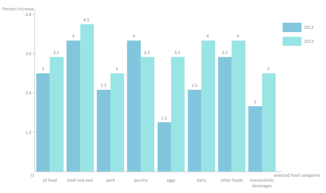
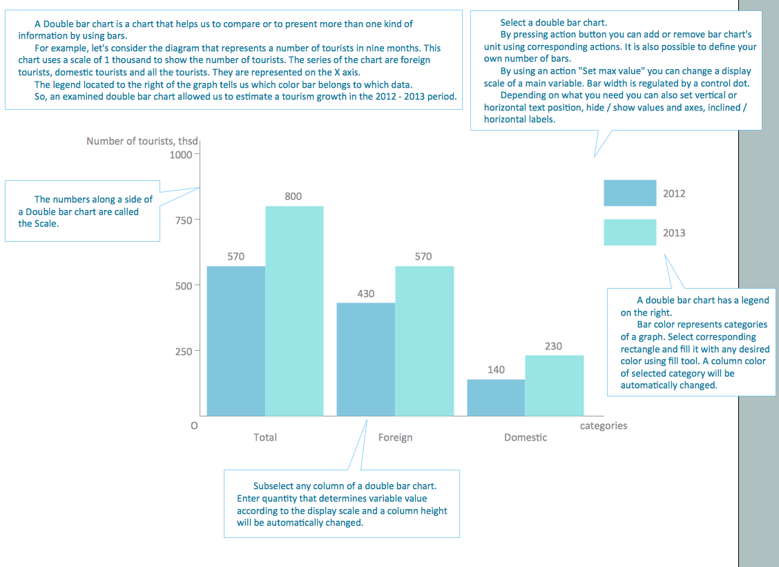
How to Create a Bar Chart
Technical Drawing Software

Chart Examples
This technical drawing shows the machine parts assembly using joining by threaded fasteners.
"Assembling (joining of the pieces) is done by welding, binding with adhesives, riveting, threaded fasteners, or even yet more bending in the form of a crimped seam. Structural steel and sheet metal are the usual starting materials for fabrication, along with the welding wire, flux, and fasteners that will join the cut pieces. As with other manufacturing processes, both human labor and automation are commonly used. The product resulting from fabrication may be called a fabrication. Shops that specialize in this type of metal work are called fab shops. The end products of other common types of metalworking, such as machining, metal stamping, forging, and casting, may be similar in shape and function, but those processes are not classified as fabrication." [Metal fabrication. Wikipedia]
This mechanical engineering drawing example was designed using ConceptDraw PRO diagramming and vector drawing software extended with Mechanical Engineering solution from Engineering area of ConceptDraw Solution Park.

Chart Templates
- Various Types Of Welding Joints With Diagram
- Types of Welding in Flowchart | Welding symbols | IDEF9 Standard ...
- Types of Welding in Flowchart | Welding And Fabrication Flow ...
- Entity Relationship Diagram Symbols | Types of Welding in ...
- Types of Welding in Flowchart | Entity Relationship Diagram ...
- Types of Welding in Flowchart | Entity Relationship Diagram ...
- Butt weld geometry | Diagram Of The Five Types Of Edges ...
- Welding Types Tree Diagram
- Types Of Welding Diagram
- Types Of Weld Joint With Diagram
- Butt weld geometry | Elements location of a welding symbol ...
- Elements location of a welding symbol | Mechanical Engineering ...
- Types of Welding in Flowchart | IDEF9 Standard | Entity Relationship ...
- Types of Welding in Flowchart | Computer Network Diagrams | 4 ...
- Types of Welding in Flowchart | Entity Relationship Diagram ...
- Types Welding Process With Flow Chart
- Types of Welding in Flowchart | Solid State Welding Diagrom ...
- Types of Flowcharts | Types of Flowchart - Overview | Types of ...
- Types of Welding in Flowchart | Interior Design Machines and ...