 ConceptDraw Solution Park
ConceptDraw Solution Park collects graphic extensions, examples and learning materials
HelpDesk
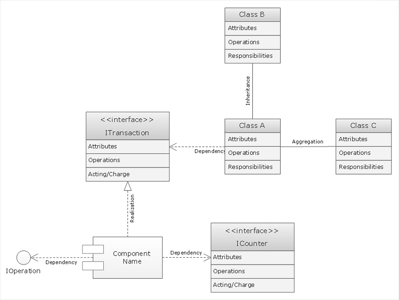
How to Create a UML Diagram Using Rapid UML Solution
ConceptDraw DIAGRAM is a perfect tool to draw UML Diagrams. The ability to create UML diagrams in ConceptDraw DIAGRAM is contained in the Rapid UML Solution. This solution provides a set of special tools for creating UML diagrams.ConceptDraw DIAGRAM Compatibility with MS Visio
The powerful diagramming and business graphics tools are now not exception, but the norm for today’s business, which develop in incredibly quick temp. But with the abundance of powerful business diagramming applications it is important to provide their compatibility for effective exchange the information between the colleagues and other people who maybe use different software in their work. During many years Microsoft Visio™ was standard file format for the business and now many people need the visual communication software tools that can read the Visio format files and also export to Visio format. The powerful diagramming and vector drawing software ConceptDraw DIAGRAM is ideal from the point of view of compatibility with MS Visio. Any ConceptDraw DIAGRAM user who have the colleagues that use MS Visio or any who migrates from Visio to ConceptDraw DIAGRAM , will not have any problems. The VSDX (Visio′s open XML file format) and VDX formatted files can be easily imported and exported by ConceptDraw DIAGRAM , you can see video about this possibility.HelpDesk
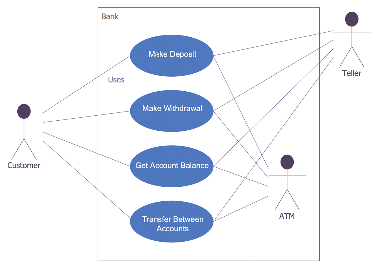
How to Create a Bank ATM Use Case Diagram
UML diagrams are often used in banking management for documenting a banking system. In particular, the interaction of bank customers with an automated teller machine (ATM) can be represented in a Use Case diagram. Before the software code for an ATM, or any other system design, is written, it is necessary to create a visual representation of any object-oriented processes. This is done most effectively by creating a Unified Modeling Language (UML) diagram, using object-oriented modeling. UML works as a general purpose modeling language for software engineers or system analysts, offering a number of different diagram styles with which to visually depict all aspects of a software system. ConceptDraw DIAGRAM diagramming software, enhanced and expanded with the ATM UML Diagrams solution, offers the full range of icons, templates and design elements needed to faithfully represent ATM and banking information system architecture using UML standards. The ATM UML Diagrams solution is useful for beginner and advanced users alike. More experienced users will appreciate a full range of vector stencil libraries and ConceptDraw DIAGRAM 's powerful software, that allows you to create your ATM UML diagram in a matter of moments.
 Business Process Diagrams
Business Process Diagrams solution extends the ConceptDraw DIAGRAM BPM software with RapidDraw interface, templates, samples and numerous libraries based on the BPMN 1.2 and BPMN 2.0 standards, which give you the possibility to visualize equally easy simple and complex processes, to design business models, to quickly develop and document in details any business processes on the stages of project’s planning and implementation.
HelpDesk
How to Make a UML Diagram
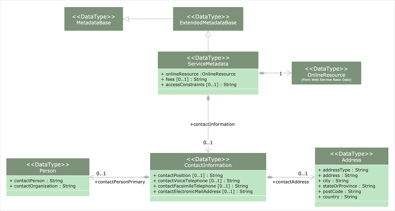
The Unified Modeling Language™(UML) is a standard visual modeling language to document business processes and software architecture. UML uses several types of diagrams including Use Case Diagrams, Class, Package, Component, Composite Structure Diagrams, Deployments, Activities, and Interactions. The accepted standard used when modeling a system is known as the Unified Modeling Language (UML), a generic set of notations that are used when creating UML diagrams. These notations can visually represent requirements, subsystems, logical and physical elements, and structural and behavioral patterns, that are especially relevant to systems built using an object-oriented style. Using UML during the modeling process has a number of benefits — for one, the entire development team can share information and collaborate using a common language, diagrams, and software, something that's not possible when using a more task-specific programming language.- UML Component Diagram Example - Online Shopping | UML Tool ...
- State Diagram Example - Online Store | UML Component Diagram ...
- ConceptDraw Solution Park | Simple Diagramming | Business ...
- Online Diagram Tool | UML Component Diagram Example - Online ...
- UML Tool & UML Diagram Examples | UML Class Diagram Example ...
- How to create your UML Diagram | UML Tool & UML Diagram ...
- UML Component Diagram Example - Online Shopping | State ...
- Diagramming Software for Design UML Activity Diagrams | UML ...
- UML Tool & UML Diagram Examples
- UML Component Diagram
- UML Tool & UML Diagram Examples
- UML Tool & UML Diagram Examples | State Diagram Example ...
- UML Tool & UML Diagram Examples | UML Diagram | Rapid UML ...
- Diagramming Software for Design UML Collaboration Diagrams ...
- UML Tool & UML Diagram Examples
- UML Deployment Diagram Example - ATM System | UML ...
- UML Use Case Diagram Example Social Networking Sites Project ...
- ConceptDraw Solution Park | UML Component Diagram Example ...
- UML Class Diagram Example for Transport System | UML Tool ...
- Diagramming Software for Design UML Component Diagrams | UML ...


