HelpDesk
How to Create an IDEF0 Diagram for an Application Development
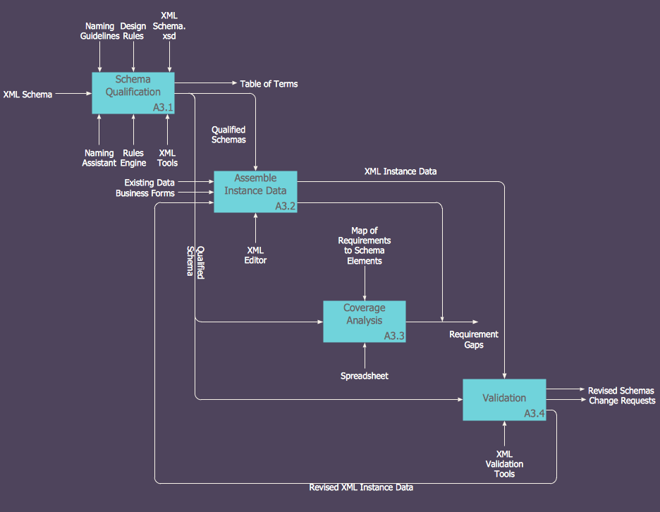
IDEF0 methods are intended to model the functions of a process, creating a graphical model that displays: what controls the function, who makes it, what resources are used and how they are connected with other functions. The IDEF0 tool is used to model the decisions, actions, and activities of a software system during the development process . IDEF0 diagram graphically depicts a model of a desired version of the application. ConceptDraw PRO allows you to create and communicate the IDEF0 diagrams of any complexity.IDEF0 standard with ConceptDraw PRO
The activity of any organization is more or less branchy network of processes. The description of these processes is a hard technical task which requires definite methodology and standards. According to the IDEF0 standard any process can be described in the form of a block (Activity Box) which has inputs and outputs. The process consists in transformation of inputs into outputs under the influence of the management and in the presence of necessary resources. Outputs of the given process later on can be either inputs for the next process or resources, or management means.Basic Flowchart Symbols and Meaning
Flowcharts are the best for visually representation the business processes and the flow of a custom-order process through various departments within an organization. ConceptDraw PRO diagramming and vector drawing software extended with Flowcharts solution offers the full set of predesigned basic flowchart symbols which are gathered at two libraries: Flowchart and Flowcharts Rapid Draw. Among them are: process, terminator, decision, data, document, display, manual loop, and many other specific symbols. The meaning for each symbol offered by ConceptDraw gives the presentation about their proposed use in professional Flowcharts for business and technical processes, software algorithms, well-developed structures of web sites, Workflow diagrams, Process flow diagram and correlation in developing on-line instructional projects or business process system. Use of ready flow chart symbols in diagrams is incredibly useful - you need simply drag desired from the libraries to your document and arrange them in required order. There are a few serious alternatives to Visio for Mac, one of them is ConceptDraw PRO. It is one of the main contender with the most similar features and capabilities.
Flowchart Software
Flowchart is a simple diagram, map or graphical schematic representation the sequence of actions within a process. It is ideal for displaying how a process currently flows or can function ideally. The Flowcharts let define the steps and boundaries of a process, uncover problems or miscommunications. The Flowcharts are widely used in education, software development, business, economics, thanks to their visuality they are ideal for presentations, reports, for using on conferences to help the audience comprehend the content better, or easy find flaws in a process flow diagrams. ConceptDraw PRO is professional flowcharts software and feature-rich flowchart maker, which supports Mac OS X and Windows. It contains at ConceptDraw Solution Park a rich set of stencils and professional flowchart symbols for design. It lets create simply professional-looking Flowcharts based on thousand free flowchart templates, colored symbols and examples. ConceptDraw PRO is a 3 times cheaper alternative to MS Visio available for both Mac and PC. It’s is another full featured business and technical diagramming application that can easily take care of Visio files within OS X. Another bonus with ConceptDraw PRO – it's cross-platform. You can work on a document in both OS X and Windows, skipping Visio entirely.
- Entity Relationship Diagram - ERD - Software for Design Crows Foot ...
- UML Class Diagram Example - Social Networking Site | UML Class ...
- Swim Lane Diagrams | Cross-Functional Flowchart (Swim Lanes ...
- Class Diagram Tool | UML Class Diagram Generalization Example ...
- UML Diagrams with ConceptDraw PRO | UML Class Diagrams ...
- UML Class Diagrams . Diagramming Software for Design UML ...
- Diagramming Software for Design UML Collaboration Diagrams ...
- Design elements - ER diagram (Chen notation) | Entity-Relationship ...
- Create UML Diagram | UML Diagrams with ConceptDraw PRO ...
- Business Processes | Booch OOD Diagram | Settlement Process ...
- UML Block Diagram | UML Class Diagram Notation | UML ...
- UML Diagram | UML Block Diagram | UML class diagram - Metadata ...
- ConceptDraw PRO Network Diagram Tool | Examples of Flowcharts ...
- UML Class Diagram Example - Medical Shop | How to create a UML ...
- Diagram Knowledge Management Plan
- ConceptDraw PRO Compatibility with MS Visio | Project Exchange ...
- Porgrams To Draw Engineering Flow Diagrams
- Entity Relationship Diagram Software for Mac | ConceptDraw PRO ...
- Total Quality Management Value | 4 Ms fishbone diagram ...
- Strategy Draw Tree Diagram


