UML Deployment Diagram Example - ATM System UML diagrams
The UML Deployment Diagram is used for visualization of elements and components of a program, that exist at the stage of its execution. It contains graphical representations of processors, devices, processes, and relationships between them. The UML Deployment Diagram allows to determine the distribution of system components on its physical nodes, to show the physical connections between all system nodes at the stage of realization, to identify the system bottlenecks and reconfigure its topology to achieve the required performance. The UML Deployment diagram is typically developed jointly by systems analysts, network engineers and system engineers. ConceptDraw PRO diagramming and vector drawing software with Rapid UML solution from Software Development area of ConceptDraw Solution Park perfectly suits for designing different types of UML diagrams, including the UML Deployment Diagrams. There are included a lot of design elements, templates, examples and samples, among them an example of work of ATM (Automated Teller Machine) banking system.Timing diagram
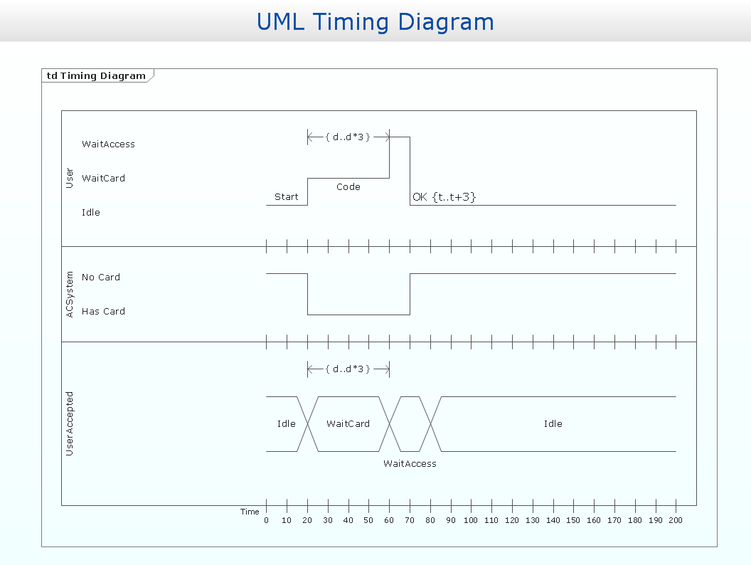
UML Timing Diagram as special form of a sequence diagram is used to explore the behaviours of objects throughout a given period of time.
State Machine Diagram
UML state machine's goal is to overcome the main limitations of traditional finite-state machines while retaining their main benefits. ConceptDraw is ideal for software designers and software developers who need to draw UML State Machine Diagrams.
Model Based Systems Engineering
ConceptDraw PRO is a professional diagramming and vector drawing software. Now, enhanced with SysML Solution from the Software Development Area of ConceptDraw Solution Park, ConceptDraw PRO became an ideal software for model based systems engineering (MBSE).JSD - Jackson system development
Jackson System Development (JSD) is a linear method of system development created by Michael A. Jackson and John Cameron in the 1980s. It comprises the whole software life cycle directly or providing a framework for more specialized techniques. When implementing the Jackson System Development method and designing JSD diagrams, you can succesfully use the powerful and helpful tools of ConceptDraw PRO software extended with Entity-Relationship Diagram (ERD) solution from the Software Development area of ConceptDraw Solution Park.- UML Use Case Diagram Example. Services UML Diagram . ATM ...
- UML Use Case Diagram Example Registration System
- Model Based Systems Engineering | JSD - Jackson system ...
- Development Decision Diagram
- UML Use Case Diagram Example Social Networking Sites Project ...
- It Software Developers Diagrams
- Usecase Diagram For Online Software Download Library System
- UML Use Case Diagram Example Registration System | Event ...
- UML Use Case Diagram Example Registration System
- Diagramming Software for Design UML Activity Diagrams | UML ...
- Earthquake disaster assessment - Workflow diagram | Workflow ...
- UML Diagrams with ConceptDraw PRO | UML Activity Diagram ...
- How To Convert a Block Diagram to Adobe PDF Using ...
- Sequence Diagram Editor
- Process Flowchart | UML Deployment Diagram . Design Elements ...
- Uml Sequence Diagram Creator
- Model Based Systems Engineering | Business Process Modeling ...
- UML Activity Diagram . Design Elements | Diagramming Software for ...
- UML Use Case Diagrams | ConceptDraw PRO UML Diagrams with ...
- UML Use Case Diagram Example Social Networking Sites Project ...


