The vector stencils library "UML communication diagrams" contains 23 symbols for the ConceptDraw PRO diagramming and vector drawing software.
"... communication diagrams use the free-form arrangement of objects and links as used in Object diagrams. In order to maintain the ordering of messages in such a free-form diagram, messages are labeled with a chronological number and placed near the link the message is sent over. Reading a communication diagram involves starting at message 1.0, and following the messages from object to object." [Communication diagram. Wikipedia]
The example "Design elements - UML communication diagrams" is included in the Rapid UML solution from the Software Development area of ConceptDraw Solution Park.
UML communication diagram symbols
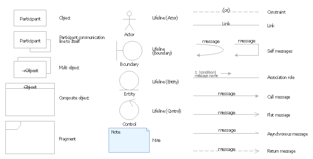
 Rapid UML
Rapid UML solution extends ConceptDraw PRO software with templates, samples and libraries of vector stencils for quick drawing the UML diagrams using Rapid Draw technology.
HelpDesk
How to Resize Objects Disproportionately in ConceptDraw PRO

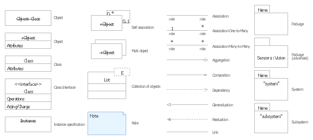
The vector stencils library "UML object diagrams" contains 26 symbols for the ConceptDraw PRO diagramming and vector drawing software.
"Each object and link on an object diagram is represented by an InstanceSpecification. This can show an object's classifier (e.g. an abstract or concrete class) and instance name, as well as attributes and other structural features using slots. Each slot corresponds to a single attribute or feature, and may include a value for that entity.
The name on an instance specification optionally shows an instance name, a ':' separator, and optionally one or more classifier names separated by commas. The contents of slots, if any, are included below the names, in a separate attribute compartment. A link is shown as a solid line, and represents an instance of an association. ...
If you are using a UML modeling tool, you will typically draw object diagrams using some other diagram type, such as on a class diagram. An object instance may be called an instance specification or just an instance. A link between instances is generally referred to as a link. Other UML entities, such as an aggregation or composition symbol (a diamond) may also appear on an object diagram." [Object diagram. Wikipedia]
The example "Design elements - UML object diagrams" is included in the Rapid UML solution from the Software Development area of ConceptDraw Solution Park.
UML object diagram symbols
HelpDesk
How to Apply the Same Formatting to Different Objects in ConceptDraw PRO

HelpDesk
How to Create a SysML Diagram Using ConceptDraw PRO
 diagram")
- UML Object Diagram. Design Elements | UML Collaboration ...
- Design elements - UML communication diagrams | UML ...
- Multi Layer Venn Diagram. Venn Diagram Example | Venn ...
- UML Package Diagram. Design Elements | Diagramming Software ...
- UML Deployment Diagram Example
- UML Component Diagram. Design Elements | How to Add Text to a ...
- Diagramming Software for Design UML Communication Diagrams ...
- Rapid UML
- Basic Flowchart Symbols and Meaning | UML Component Diagram ...
- How to Add Text to a Connector in ConceptDraw PRO | UML ...
- UML Component Diagram. Design Elements | Basic Flowchart ...
- UML Class Diagram Example - Medical Shop | Planogram Software ...
- UML Use Case Diagram Example Social Networking Sites Project ...
- How to Create a Bank ATM Use Case Diagram Using ConceptDraw ...
- How to create a UML Diagram | UML Class Diagram. Design ...
- Class UML Diagram for Bank Account System | UML package ...
- Sequence Diagram Tool | Cross-Functional Flowchart | UML ...
- Design elements - UML communication diagrams
- UML Object Diagram. Design Elements | Business Process ...