Jacobson Use Cases Diagram
The vector stencils library UML Use Case contains specific symbols of the UML notation such as actors, actions, associations and relationships for the ConceptDraw DIAGRAM diagramming and vector drawing software. This library is contained in the Rapid UML solution from Software Development area of ConceptDraw Solution Park.UML Class Diagram Generalization Example UML Diagrams
This sample was created in ConceptDraw DIAGRAM diagramming and vector drawing software using the UML Class Diagram library of the Rapid UML Solution from the Software Development area of ConceptDraw Solution Park. This sample describes the use of the classes, the generalization associations between them, the multiplicity of associations and constraints. Provided UML diagram is one of the examples set that are part of Rapid UML solution.
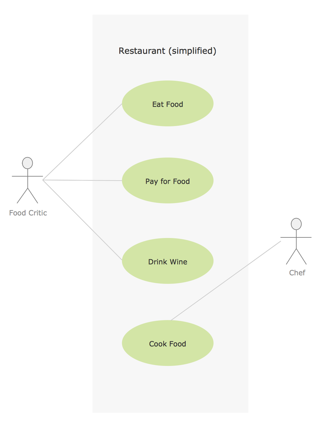
This SysML diagram example was redesigned from Wikimedia Commons file: Use case restaurant model.svg.
"Use case model of a restaurant business." [commons.wikimedia.org/ wiki/ File:Use_ case_ restaurant_ model.svg]
"The use case diagram describes the usage of a system (subject) by its actors (environment) to achieve a goal, that is
realized by the subject providing a set of services to selected actors. The use case can also be viewed as functionality and/
or capabilities that are accomplished through the interaction between the subject and its actors. Use case diagrams include the use case and actors and the associated communications between them. Actors represent classifier roles that are external to the system that may correspond to users, systems, and or other environmental entities. They may interact either directly or indirectly with the system. The actors are often specialized to represent a taxonomy of user types or external systems." [omg.org/ spec/ SysML/ 1.3/ ]
The SysML diagram example "Use case restaurant model" was drawn using the ConceptDraw PRO diagramming and vector drawing software extended with the SysML solution from the Software Development area of ConceptDraw Solution Park.
UML Collaboration Diagram Example Illustration
UML Collaboration Diagram Example Illustration. This sample was created in ConceptDraw DIAGRAM diagramming and vector drawing software using the UML Collaboration Diagram library of the Rapid UML Solution from the Software Development area of ConceptDraw Solution Park. This sample shows the creation process of the contact list and can be used at the staff training and staff working, at the attraction process the new clients.Use Case Diagrams technology with ConceptDraw DIAGRAM
Use case diagrams are used at the development of software and systems for definition of functional system requirements or system of systems. Use case diagram presents the consecution of object’s actions (user’s or system’s) which are executed for reaching the definite result.Financial Trade UML Use Case Diagram Example
This sample represents the actors, use cases and dependencies between them, and also the relationships between use cases. There are used dependency and use case generalization associations on this UML diagram. Use case generalization is used when you have two similar use cases, but one of them does more than another. This sample shows the work of the Financial Trade sphere and can be used by trading companies, commercial organizations, traders, different exchanges.UML Use Case Diagram Example. Registration System
This sample was created in ConceptDraw DIAGRAM diagramming and vector drawing software using the UML Use Case Diagram library of the Rapid UML Solution from the Software Development area of ConceptDraw Solution Park. This sample shows the types of user’s interactions with the system and is used at the registration and working with the database system.UML Class Diagram Tutorial
The Rapid UML Solution from the Software Development area of ConceptDraw Solution Park helps you to create the UML Class Diagrams quick and easy using ConceptDraw DIAGRAM diagramming and vector drawing software.Model Based Systems Engineering
ConceptDraw DIAGRAM is a professional diagramming and vector drawing software. Now, enhanced with SysML Solution from the Software Development Area of ConceptDraw Solution Park, ConceptDraw DIAGRAM became an ideal software for model based systems engineering (MBSE).Sample for UML
This sample was created in ConceptDraw DIAGRAM diagramming and vector drawing software using the UML Use Case Diagram library of the Rapid UML Solution from the Software Development area of ConceptDraw Solution Park.Create Sophisticated Professional Diagrams - Simply
ConceptDraw DIAGRAM is a powerful software that helps you create professional and easy drawing diagrams for business, technology, science and education.
SYSML
The SysML solution helps to present diagrams using Systems Modeling Language; a perfect tool for system engineering.
Network Diagram Software. LAN Network Diagrams. Physical Office Network Diagrams
Physical LAN Diagrams illustrate the communication schemes of Local Area Networks, the physical network connection of computers and networks arrangement on the small areas - at homes, offices, and other buildings. ConceptDraw DIAGRAM is a perfect network diagramming software with samples and examples of WAN and LAN Diagrams, templates and collection of network components libraries. Computer Network Diagrams Solution for ConceptDraw DIAGRAM Mac and Windows is ideal for IT professionals, network engineers and network designers who need to visualize network architecture, to document LANs physical structure and arrangement, to draw Local Area Network (LAN) diagrams and schematics, WAN diagrams, physical office network diagrams and topologies, wiring drawings, etc. You can design all them easy using the predesigned vector objects of computers and computer network devices, hardware devices, peripheral devices, external digital devices, internet and logical symbols, and many other stencils from the Computer Network Diagrams libraries. ConceptDraw DIAGRAM offers a powerful and easy-to-use solution for those who looking for a Visio alternative for Mac. It is a world-class diagramming platform with dynamic presentation power.
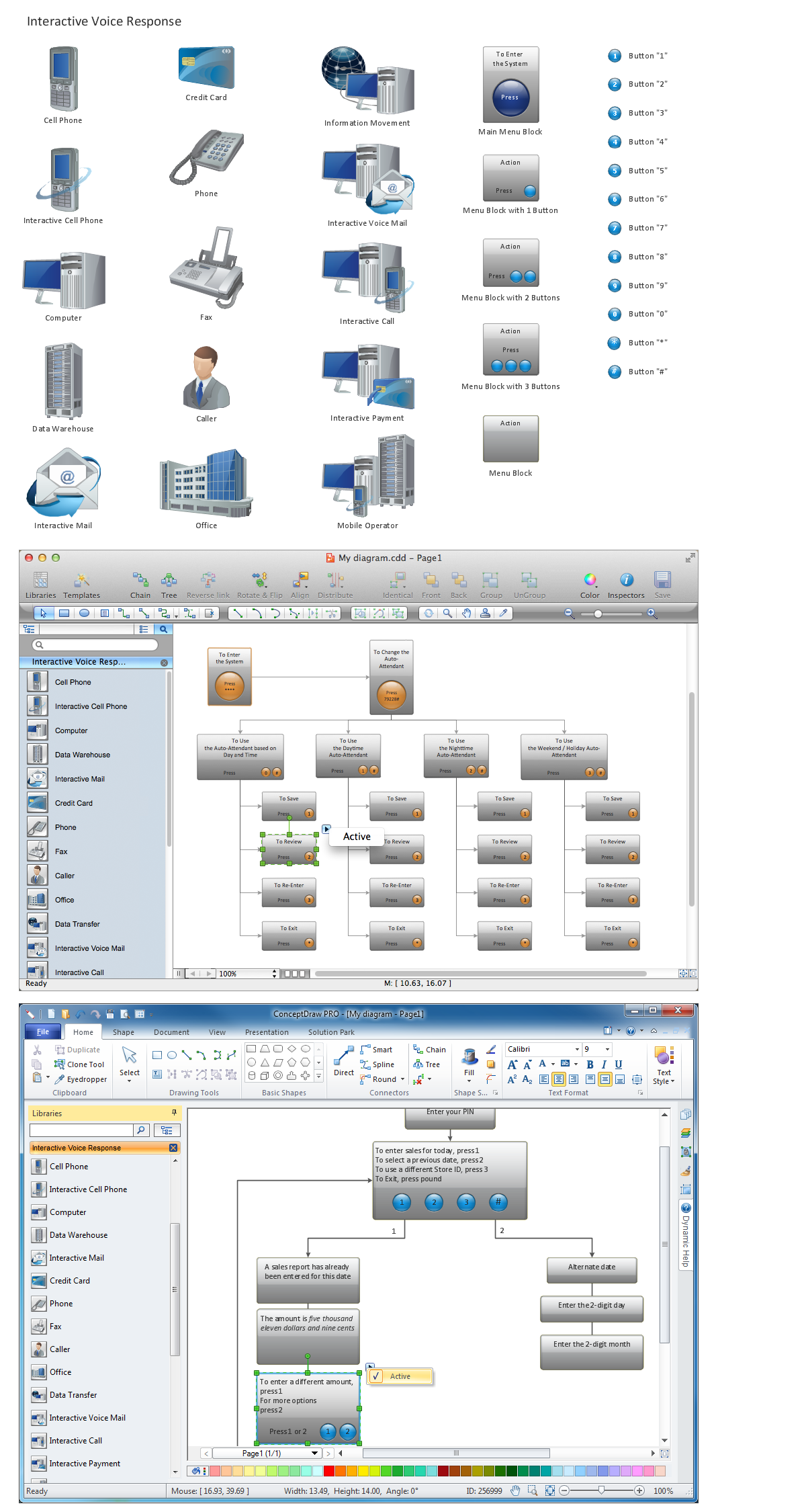
Network Diagramming Software for Design IVR Network Diagrams
ConceptDraw DIAGRAM is perfect for software designers and software developers who need to draw IVR Network Diagrams.
Sign Making Software
ConceptDraw DIAGRAM is a powerful sign making software thanks to the vector stencils library "Recreation signs". This library is included in the Directional Maps solution from the Maps area of ConceptDraw Solution Park. Sign making software is very useful tool for professional sign-making business. Use ConceptDraw DIAGRAM and make sure that now sign making is easier and timesaving than ever!- Usecase Diagram For Restaurant System
- Restaurant For Use Case Diagram And Data Flow Diagram
- Restaurant Software Usecase Diagram
- Data Flow Diagrams (DFD) | Jacobson Use Cases Diagram | Model ...
- Use Case Diagram For Restaurant Automation System
- Jacobson Use Cases Diagram | Cafe and Restaurant Floor Plans ...
- Jacobson Use Cases Diagram | Use case restaurant model | Use ...
- Jacobson Use Cases Diagram | Use case restaurant model | UML ...
- Use Case Diagram For A Restaurant System
- Army Flow Charts | Jacobson Use Cases Diagram | Model Based ...
- Use case restaurant model | Use Case Diagrams technology with ...
- Jacobson Use Cases Diagram | Financial Trade UML Use Case ...
- Use Case Diagrams Restaurant Management System Actors
- Jacobson Use Cases Diagram | Model Based Systems Engineering ...
- Jacobson Use Cases Diagram | Use case restaurant model | Cafe ...
- Use Case Diagram Restaurant Management System
- Use Case Diagram Of Restaurant Management
- Use case restaurant model | Jacobson Use Cases Diagram | How ...
- Diagramming Software for Design UML Use Case Diagrams | UML ...
- Uml Diagrams Of Restaurant Management System