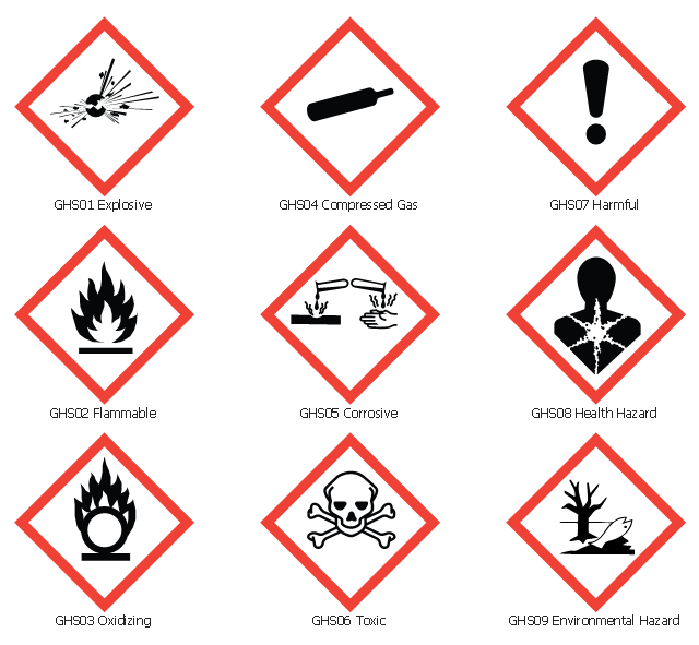
The vector stencils library "GHS hazard pictograms" contains 9 chemical hazard symbols.
Use it in ConceptDraw PRO software to design your chemical safety infographics, labels of containers with hazardous materials, International Chemical Safety Cards (ICSC), manufacturers' Safety Data Sheets (SDS), and Material Safety Data Sheets (MSDS).
"Hazard pictograms form part of the international Globally Harmonized System of Classification and Labelling of Chemicals (GHS). Two sets of pictograms are included within the GHS: one for the labelling of containers and for workplace hazard warnings, and a second for use during the transport of dangerous goods. ...
Hazard pictograms are one of the key elements for the labelling of containers under the GHS, along with:
- an identification of the product;
- a signal word – either Danger or Warning – where necessary;
- hazard statements, indicating the nature and degree of the risks posed by the product;
- precautionary statements, indicating how the product should be handled to minimize risks to the user (as well as to other people and the general environment);
- the identity of the supplier (who might be a manufacturer or importer)." [GHS hazard pictograms. Wikipedia]
The chemical hazard symbols example "Design elements - GHS hazard pictograms" is included in the GHS Hazard Pictograms solution from the Engineering area of ConceptDraw Solution Park.
Chemical safety symbols
Hazard Pictograms

Cisco Network Icons
Mechanical Drawing Symbols

 Transport Hazard Pictograms
Transport Hazard Pictograms solution includes large variety of specially developed samples with transport hazard symbols and pictograms, and the whole set of predesigned vector transport GHS pictograms download and used with ease from the Transport Hazard Pictograms library. Apply them for quick designing professional-looking infographics and diagrams, use them to create warning signboards and announcements on all stages of the transportation process, to place them on the transport vehicles and warehouses of transportation companies, at the transport documentation and on the websites of transport and logistics companies.
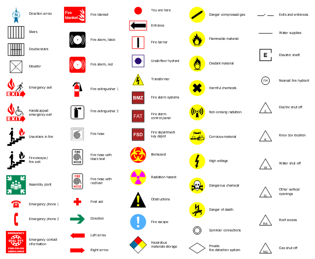
The design elements library "Fire and emergency planning" contains 58 fire safety symbols for developing the fire escape plans using the ConceptDraw PRO diagramming and vector drawing software.
The fire escape plan shows the location of fire alarm and extinguishing equipment, stairs and emergency exits, and evacuation orders and path.
"Hazard symbols are recognizable symbols designed to warn about hazardous materials, locations, or objects, including electric currents, poisons, and other things. The use of hazard symbols is often regulated by law and directed by standards organizations. Hazard symbols may appear with different colors, backgrounds, borders and supplemental information in order to specify the type of hazard." [Hazard symbol. Wikipedia]
The vector stencils library Fire and emergency planning is included in the Fire and Emergency Plans solution from the Building Plans" area of ConceptDraw Solution Park.
Safety symbols
Network Security Devices

The vector stencils library "Valves and fittings" contains 104 symbols of valve components.
Use these icons for drawing industrial piping systems; process, vacuum, and fluids piping; hydraulics piping; air and gas piping; materials distribution; and liquid transfer systems.
"A valve is a device that regulates, directs or controls the flow of a fluid (gases, liquids, fluidized solids, or slurries) by opening, closing, or partially obstructing various passageways. Valves are technically valves fittings, but are usually discussed as a separate category. In an open valve, fluid flows in a direction from higher pressure to lower pressure.
The simplest, and very ancient, valve is simply a freely hinged flap which drops to obstruct fluid (gas or liquid) flow in one direction, but is pushed open by flow in the opposite direction. This is called a check valve, as it prevents or "checks" the flow in one direction. ...
Valves are found in virtually every industrial process, including water & sewage processing, mining, power generation, processing of oil, gas & petroleum, food manufacturing, chemical & plastic manufacturing and many other fields. ...
Valves may be operated manually, either by a handle, lever, pedal or wheel. Valves may also be automatic, driven by changes in pressure, temperature, or flow. These changes may act upon a diaphragm or a piston which in turn activates the valve, examples of this type of valve found commonly are safety valves fitted to hot water systems or boilers.
More complex control systems using valves requiring automatic control based on an external input (i.e., regulating flow through a pipe to a changing set point) require an actuator. An actuator will stroke the valve depending on its input and set-up, allowing the valve to be positioned accurately, and allowing control over a variety of requirements." [Valve. Wikipedia]
The example "Design elements - Valves and fittings" was created using the ConceptDraw PRO diagramming and vector drawing software extended with the Chemical and Process Engineering solution from the Engineering area of ConceptDraw Solution Park.
Valves and fittings symbols

Electrical Symbols — Switches and Relays

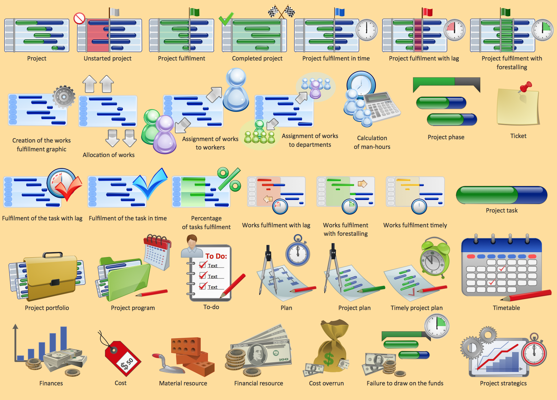
Project management - Design Elements
 Chemistry
This solution extends ConceptDraw DIAGRAM software with samples, template and libraries of vector stencils for drawing the Chemistry Illustrations for science and education.
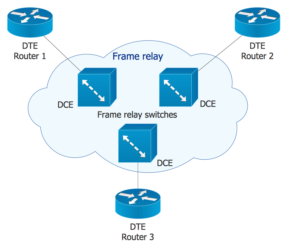
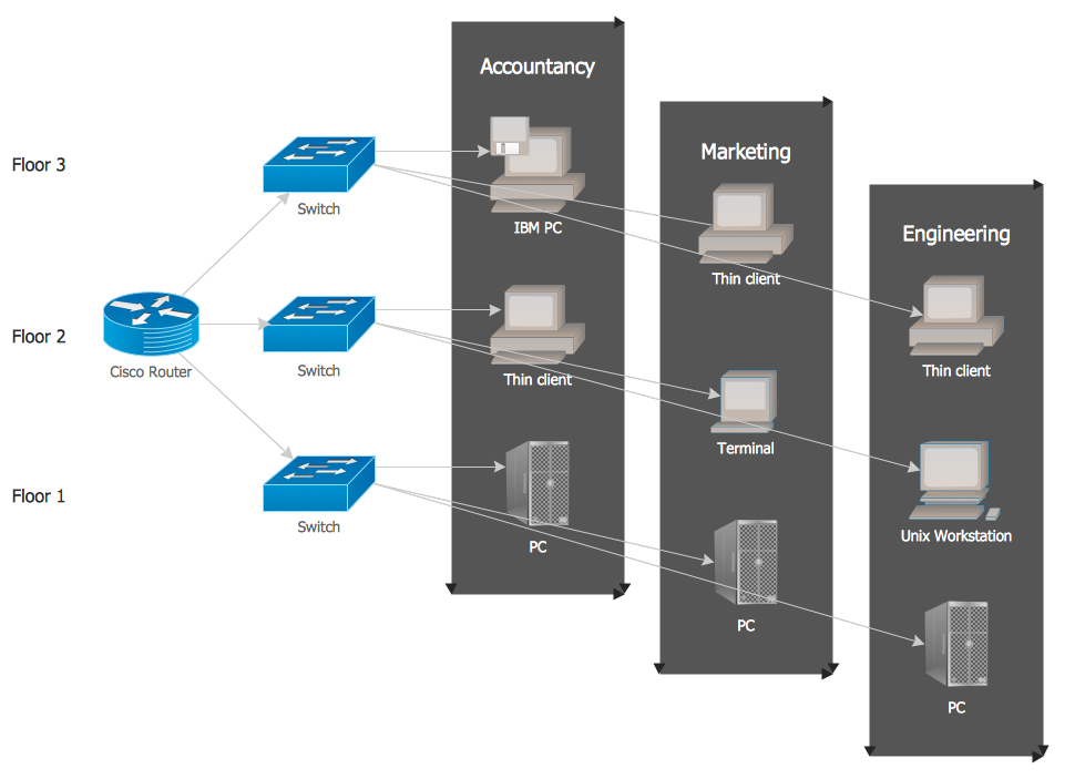
Local network area. Computer and Network Examples

The vector stencils library "Valves and fittings" contains 104 symbols of valve components.
Use these icons for drawing industrial piping systems; process, vacuum, and fluids piping; hydraulics piping; air and gas piping; materials distribution; and liquid transfer systems in the ConceptDraw PRO software extended with the Chemical and Process Engineering solution from the Chemical and Process Engineering area of ConceptDraw Solution Park.
www.conceptdraw.com/ solution-park/ engineering-chemical-process
Electrically bonded

Bursting disc

Flame arrester

Strainer

Separator

Exhaust silencer

Bell mouth

Exhaust head

Hydrant

Drain silencer

Liquid seal open/closed

Y strainer

Gate valve

Globe valve

Globe valve 2

Globe valve 3

Screw-down valve

Lock-shield valve

Reel valve

Check valve

Check valve 2

Check valve 3

Screw-down check valve

Stop check valve

Diaphragm valve

Diaphragm valve 2

Diaphragm valve 3

Powered valve

Powered valve 2

Powered valve 3

Needle valve

Needle valve 2

Needle valve 3

Relief valve

Relief valve 2

Relief valve 3

Angle valve

Angle valve 2

Angle valve 3

Angle valve 4

Float operated valve

Float operated valve 2

Flanged valve

Butterfly valve

Butterfly valve 2

Wedge gate valve

Parallel slide valve

Ball valve

Ball valve 2

Ball valve 3

Relief angle valve vacuum

Relief angle valve pressure

Reducing valve

Reducing valve 2

Plug valve 3 way

Plug valve L point

Plug valve 2

Plug valve

Plug valve straight through

Plug valve T point

3-way plug valve

3-way plug valve 2

3-way plug valve 3

Mixing valve

Valve Manifold

Characterized port valve

Reducer

Reducer 2

General joint

Butt weld

Butt weld 2

Butt weld 3

Butt weld 4

Flanged/ bolted

Soldered / solvent

Soldered / solvent 2

Screwed joint

Screwed joint 2

Screwed joint 3

Socket and spigot

Socket and spigot 2

Socket and spigot 3

Sleeve

Sleeve 2

Screwed sleeve

Screwed sleeve 2

Socket weld

Socket weld 2

Swivel joint

Swivel joint 2

Swivel joint 3

End cap

End cap butt welded

End cap screwed

End cap socket and spigot

End cap fillet welded

End cap screwed and plugged

End cap quick release

End cap flanged and bolted

End cap flanged and bolted 2

Electrically insulated

Tundish

Syphon drain

Open vent

ConceptDraw DIAGRAM Compatibility with MS Visio

- GHS Hazard Pictograms | Fire and emergency planning - Vector ...
- Clipart Safety Chemical Signs
- Chemistry Symbols and Meanings | Flowchart design. Flowchart ...
- Safety and Security | Fire safety equipment - Vector stencils library ...
- Electrical Symbols — Electrical Circuits | Electrical circuits - Vector ...
- Management pictograms - Vector stencils library | GHS Hazard ...
- Design elements - GHS hazard pictograms | GHS HAZCOM Safety ...
- People pictograms - Vector stencils library | Business people ...
- Design elements - Periodic table of chemical elements | Design ...
- Health Safety Environment Symbol
- Process Flow Diagram Symbols | Organic Chemistry Symbols ...
- Hazard Chemical Sign | GHS Hazard Pictograms | Fire and ...
- Examples Of Standard Safety Symbol In Laboratory And Its Importance
- GHS Hazard Pictograms | GHS hazard symbols | Design elements ...
- GHS Hazard Pictograms | Transport Hazard Pictograms | Hazard ...
- Design elements - GHS hazard pictograms | GHS Label Pictograms ...
- Design Pictorial Infographics. Design Infographics | How to Draw ...
- Chemical Industry Safety To Draw Diagram
- Fire and emergency planning - Vector stencils library | Gas ...
- Laboratory equipment - Vector stencils library | Chemistry Symbols ...