Electrical Drawing Software and Electrical Symbols

Basic Diagramming


Technical Drawing Software

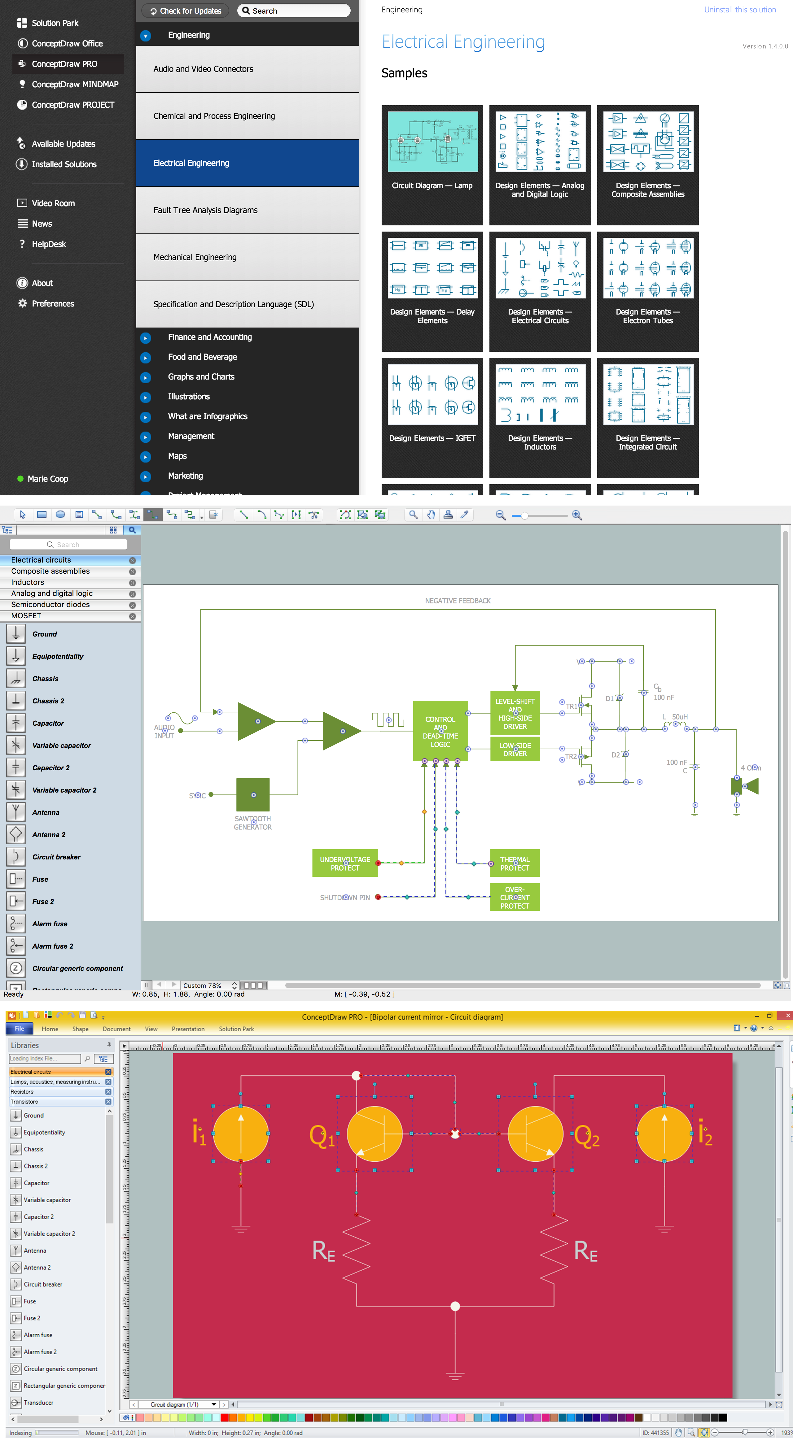
 Electrical Engineering
This solution extends ConceptDraw DIAGRAM.9.5 (or later) with electrical engineering samples, electrical schematic symbols, electrical diagram symbols, templates and libraries of design elements, to help you design electrical schematics, digital and analog
How To use House Electrical Plan Software


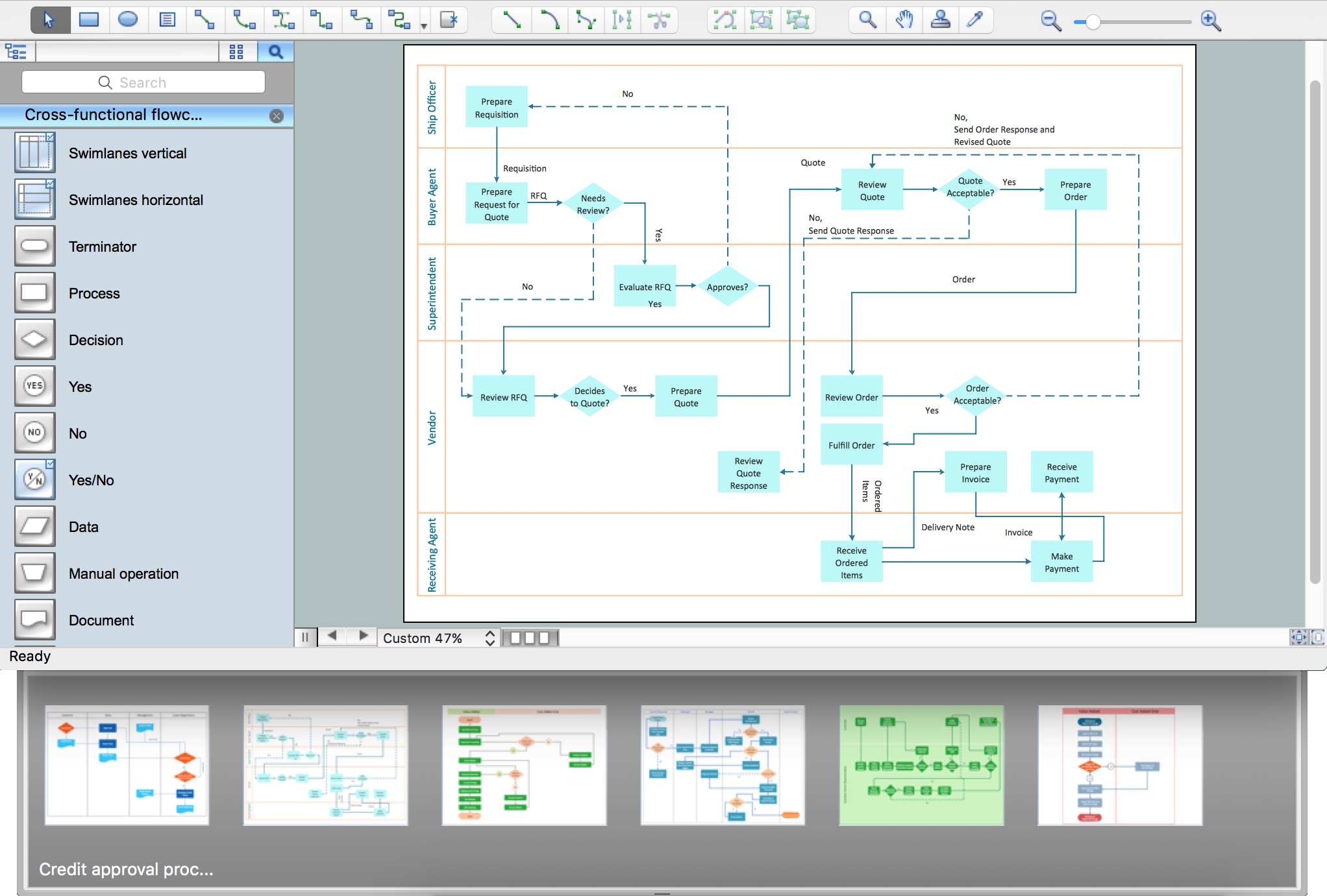
Process Flowchart

Piping and Instrumentation Diagram Software

 Vehicular Networking
The Vehicular Networking solution extends the ConceptDraw DIAGRAM software functionality with specialized tools, wide variety of pre-made vector objects, collection of samples and templates in order to help network engineers design vehicular network diagrams for effective network engineering activity, visualize vehicular networks, develop smart transportation systems, design various types of vehicle network management diagrams, regional network diagrams, vehicular communication system diagrams, vehicular ad-hoc networks, vehicular delay-tolerant networks, and other network engineering schemes.
Electrical Symbols, Electrical Diagram Symbols

Wiring Diagrams with ConceptDraw DIAGRAM
- Car Electrical Wiring Diagram Software Free Download
- Electrical Drawing Software and Electrical Symbols | How To use ...
- Car Wiring Diagram Software Download
- Electrical Drawing Software and Electrical Symbols | Electrical ...
- Electrical Drawing Software and Electrical Symbols | How To use ...
- Automotive Wiring For All Make Car Software
- Electrical Wiring System In Car Video Download
- Electrical Layout Drawing Software Free Download
- Car Diagram Software
- Electronic Circuit Diagram Assemblies Free Video Download