This site uses cookies. By continuing to browse the ConceptDraw site you are agreeing to our Use of Site Cookies.

What is a Virtual Private Network?
VPN Diagram Examples

A Virtual Private Network (VPN) is a network that allows the private networks at a remote location securely connect to the public Internet and provide access only to the intended recipients for transmitting data. VPN is built by creating the virtual point-to-point connection using the dedicated connections, traffic encryption or virtual tunneling protocols. This example was created in ConceptDraw DIAGRAM using the Computer and Networks Area of ConceptDraw Solution Park and shows the Virtual Private Network (VPN) diagram.

Virtual networks. Computer and Network Examples

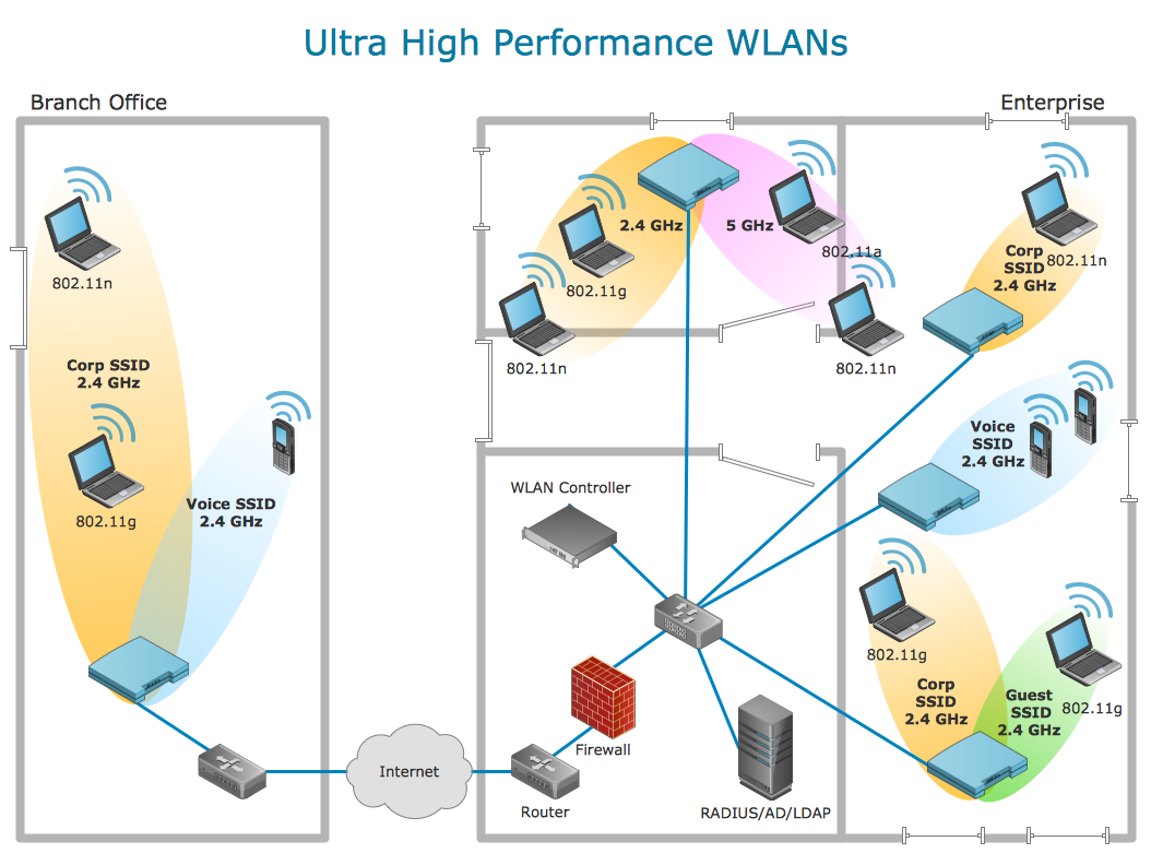
A Virtual network is a computer network that consists of virtual network links, i.e. between the computing devices there isn't a physical connection. Well known forms of network virtualization are virtual networks based on the virtual devices (for example the network based on the virtual devices inside a hypervisor), protocol-based virtual networks (VLAN, VPN, VPLS, Virtual Wireless network, etc.) and their combinations. This example was created in ConceptDraw DIAGRAM using the Computer and Networks Area of ConceptDraw Solution Park and shows the Virtual network.

Technical Flow Chart Example

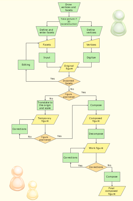
What illustrates a technical flow chart? Technical flow chart is a diagrammatic representation which visually illustrates the sequence of operations that must to be performed to get the problem's solution. ConceptDraw DIAGRAM enhanced with Flowcharts Solution from the "Diagrams" Area of ConceptDraw Solution is a perfect software for drawing Technical Flow Chart Example illustrating the essence and importance of the technical flow chart use.

Telecommunication networks. Computer and Network Examples

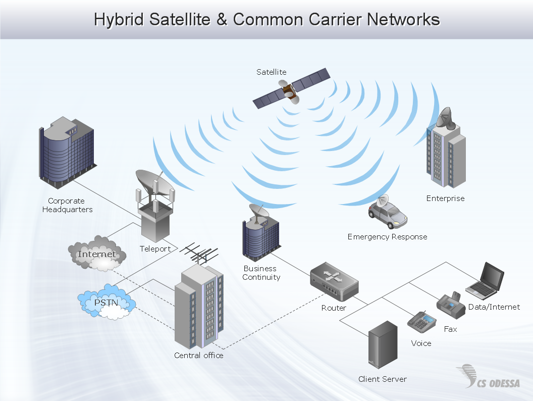
A Telecommunications network is a network of nodes, links, trunks and telephone switches that are connected, operated by telephone companies and realize telephone, audio, visual and data communications among the users. The telecommunications network can also include Internet, microwave, wireless equipment. This example was created in ConceptDraw DIAGRAM using the Computer and Networks Area of ConceptDraw Solution Park and shows the Telecommunications network.

Network Security

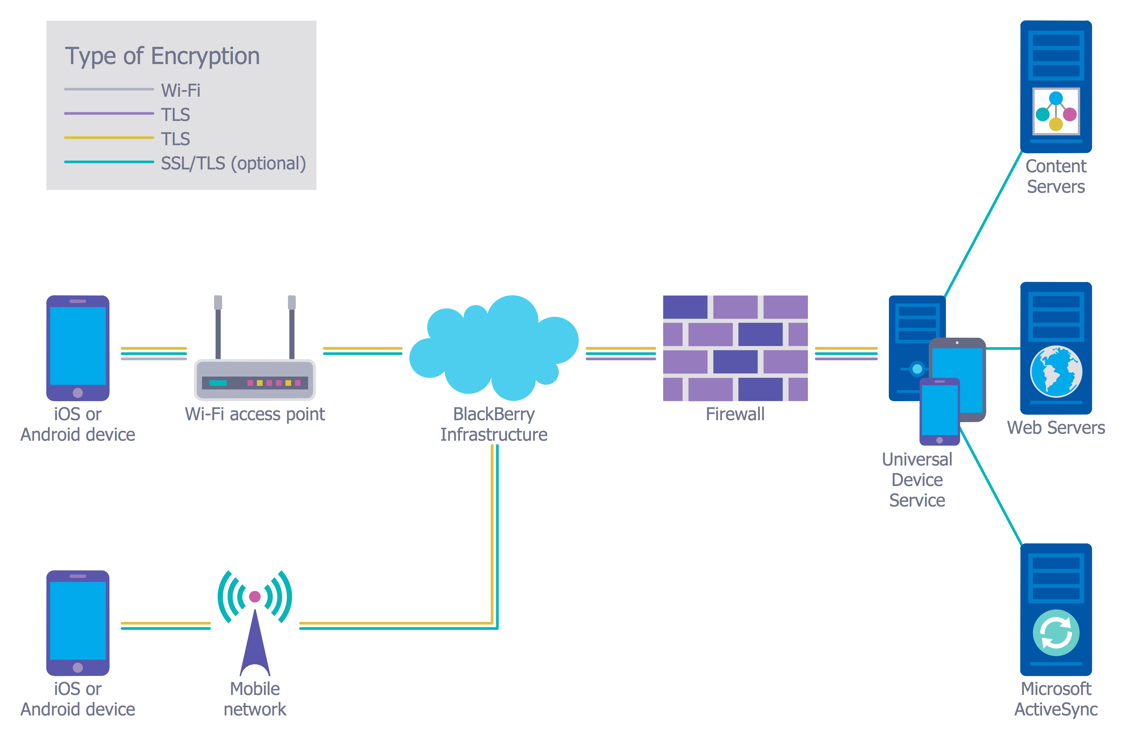
The Internet is a giant computer network which connects computers all over the world. It is integral part of human society and business. But the serious question for network engineers, designers, lawmakers and enforcers is the need for protect the Internet networks from the Internet crimes, hacking and attacks. There are quite a number of hardware, software and physical methods of protection against them. The samples you see on this page were created in ConceptDraw DIAGRAM using the tools of Network Security Diagrams Solution for ConceptDraw DIAGRAM software. They show protection networks with Firewalls and other network security devices.

Steel Presentation

The presentation clearly shows the attractiveness of the project, product or service, its strengths, the irrefutable advantages and compelling arguments. The success of presentation depends on the competent combination of text with high-quality visual design. It is recommended to represent a moderate amount of text and supplement it by attractive and stylish images, photos, graphs and diagrams. However, they do not necessarily have to be bright, in some cases vice versa is appropriate to withstand a discreet, strict and business steel style, especially when you need that design of presentation did not distract from the main content of the project. The background should have the soothing color shade, which will not prevent to perception of information, and the font should to be large and clear, without unnecessary fanciful elements. ConceptDraw MINDMAP software lets create attractive Mind Maps and ConcepDraw DIAGRAM software helps design professional-looking diagrams, infographics and illustrations, that you can then output in one click to MS Power Point presentation. Create quickly and easily the most informative and memorable presentations with ConceptDraw Office applications.

Network Architecture

Network architecture is a design of the structure of communication network. Network architecture specifies network configuration, the main physical components of the network, products and services delivered via communication network, defines the components that characterize its common logical organization, technical support, software. It describes encoding methods, principles of operation and user interface. To graphically represent the network is used a Network Architecture Diagram. ConceptDraw DIAGRAM software is the best network diagramming tool that lets create in minutes your own professional Network diagrams from numerous templates and examples. Computer & Networks solution for ConceptDraw DIAGRAM software provides extensive libraries of vector stencils for drawing Network architecture diagrams and maps, Cisco network architectural drawings, Computer communication network design blueprints, TCP/IP network architecture diagrams for LANs and WANs, Network floor plan layouts, Logical network diagrams, Network communication plans, Web-based network diagrams, etc.

Guesthouse Network. How to get Internet in guest house

Computer and Networks solution provides examples, templates and vector stencils library with symbols of local area network (LAN) and wireless LAN (WLAN) equipment. This example shows the computer network diagram of the guesthouse connection to the Internet. You can see the needed equipment on the diagram and how it must be arranged to get the Internet in any point of the guesthouse.

UML Notation

Unified Modeling Language (UML) is an open standard, the language of graphic description used for modeling objects in a field of software development and software engineering. It was created for definition, specification, visualization, designing and documenting software systems, as a unification of three object-oriented technologies Booch, OMT and OOSE, and uses the defined graphic notation for creating the visual models of object-oriented software systems. Description of UML consists of two parts, interactive and supplementing each other: UML semantics, which represents a certain metamodel, defines the abstract syntax and semantics of terms of object modeling with UML, and UML notation that is a graphic notation for visual representation of UML semantics. The powerful tools of the Rapid UML solution included to ConceptDraw Solution Park make the ConceptDraw DIAGRAM diagramming and vector drawing software the best for easy applying the UML notation when creating the visual models of object-oriented software systems and designing different kinds of UML diagrams.

Complete Network Topology

This sample was created in ConceptDraw DIAGRAM diagramming and vector drawing software using the Computer and Networks solution from Computer and Networks area of ConceptDraw Solution Park. A complete (fully connected) topology is a network topology in which there is a direct link between all pairs of nodes. In a fully connected network with n nodes, there are n(n-1)/2 direct links. Networks designed with this topology are usually very expensive to set up, but provide a high degree of reliability due to the multiple paths for data that are provided by the large number of redundant links between nodes.

Cisco Products Additional. Cisco icons, shapes, stencils and symbols

The ConceptDraw vector stencils library Cisco Products Additional contains equipment symbols for drawing the computer network diagrams.
The vector stencils library "AWS Compute and Networking" contains 23 Amazon Web Services compute and networking icons: Amazon Elastic Compute Cloud symbols, Amazon Virtual Private Cloud symbols, Amazom Route 53 symbols, Elastic Load Balancing symbol, AWS Direct Connect symbol, Auto Scaling symbol, Elastic Network Instance symbol. Use it to draw AWS architecture diagrams of your cloud service. The symbols example "AWS Compute and Networking - Vector stencils library" was created using the ConceptDraw PRO diagramming and vector drawing software extended with the AWS Architecture Diagrams solution from the Computer and Networks area of ConceptDraw Solution Park.
Amazon EC2
Amazon EC2, Amazon EC2,
Instance
Instance, instance,
Instances
Instances, instances,
AMI
AMI, AMI,
DB on instance
DB on instance, DB on instance,
Instance with CloudWatch
Instance with CloudWatch, Instance with CloudWatch,
Elastic IP
Elastic IP, Elastic IP,
Optimized instance
Optimized instance, optimized instance,
Amazon Lambda
Amazon Lambda, Amazon Lambda,
Amazon VPC
Amazon VPC, Amazon VPC,
Router
Router, router,
Internet gateway
Internet gateway, internet gateway,
Customer gateway
Customer gateway, customer gateway,
Virtual private gateway
Virtual private gateway, virtual private gateway,
VPN connection
VPN connection, VPN connection,
VPC peering
VPC peering, VPC peering,
Amazon Route 53
Amazon Route 53, Amazon route 53,
Hosted zone
Hosted zone, hosted zone,
Route table
Route table, route table,
Elastic Load Balancer
Elastic Load Balancer, elastic load balancer,
AWS Direct Connect
AWS Direct Connect, AWS direct connect,
Auto Scaling
Auto Scaling, auto scaling,
Elastic network instance
Elastic network instance, elastic network instance,

Network Topologies

Network topology is a topological structure of computer network, which can be physical or logical. The physical topology depicts location of different computer network elements such as computers, cables and other devices. The logical topology visually displays network dataflows from one device to another. Sometimes network logical and physical topologies can be the same. ConceptDraw DIAGRAM diagramming and vector drawing software is powerful for drawing network maps and network topologies diagrams of any kinds and complexity thanks to the Computer Network Diagrams solution from the Computer and Networks area. ConceptDraw STORE proposes collection of network icons libraries and a lot of Network Topology Diagram examples, samples and templates which were created at ConceptDraw DIAGRAM software specially for Computer Network Diagrams solution. There are six basic types of the network topologies: Bus, Star, Ring, Mesh, Tree, Fully Connected. You can fast and easy design professional-looking diagram for each of them using the ConceptDraw DIAGRAM tools. There are plenty of web Visio-like diagramming software available. Web based diagrams software can be powerful, but sometimes it is essential to have desktop software. One of the most advanced diagrams tools like Visio for Mac OS is ConceptDraw DIAGRAM app.
Create Network Topology Diagram

network security tips, cyber security degrees, it security solutions, network security, network security devices, secure wireless network Network Security Diagrams

network security tips, cyber security degrees, it security solutions, network security, network security devices, secure wireless network
The Network Security Diagrams solution presents a large collection of predesigned cybersecurity vector stencils, cliparts, shapes, icons and connectors to help you succeed in designing professional and accurate Network Security Diagrams, Network Security Infographics to share knowledge about effective ways of networks protection with help of software and network security devices of different cyber security degrees, Network Plans for secure wireless network, Computer Security Diagrams to visually tell about amazing possibilities of IT security solutions. The samples and examples reflect the power of ConceptDraw DIAGRAM software in drawing Network Security Diagrams, give the representation about variety of existing types of attacks and threats, help to realize their seriousness and the methods to deal with them.

Cloud Computing Architecture

The Cloud Computing Architecture is the structure of the system, which is based on the needs of end-user and includes the set of components and subcomponents required for cloud computing, among them cloud resources, services, middleware, software components, front-end platforms (cloud clients), cloud-based back end platforms (servers, storage), and a network (Internet, Intranet, Intercloud). When designing the Cloud Computing Architecture diagrams, the ConceptDraw DIAGRAM diagramming and vector drawing software advises to turn attention for the powerful Cloud Computing Diagrams solution from the extensive Computers and Network area of ConceptDraw Solution Park.
HelpDesk

How to Create a Network Security Diagram

Network security requires constant work and attention to details. Each user, whether an individual or organization, owns a piece of information, considered to be valuable. The enforcement of network security, whether it be local network security, or wireless network security is the core for creating the secure environment of the daily working processes. Network security is accomplished through hardware and software. The network security system must be sophisticated and modern inside, but simple and understandable for the user. The visual scheme of a security system can be presented in the form of a Network Security diagram. ConceptDraw DIAGRAM provides the toolkit for network security system visualization with its Network Security Diagram solution.

Bus Network Topology

Bus Network Topology is a network topology that represents one shared cable (called a bus or backbone) to which are directly connected all workstations or computers of the network. At the ends of the cable are situated the terminators for prevention the signal reflection. All workstations at Bus Network Topology have equal rights and transfer the information sequentially, one after another. The message sent by one of workstations is extended on all computers of the network and each computer checks to whom it is addressed, if for him, then processes it. Addition of new subscribers to the "bus" is quite simple, the failures of individual computers are not dangerous, and the lack of a central subscriber even more increases its reliability. Computer and Networks solution included to Computer and Networks area of ConceptDraw Solution Park offers templates, samples and numerous vector stencils libraries that can be used to effectively design different physical and logical network topologies diagrams for wireless and wired computer networks, including Bus Network Topology.

Cisco networking, Cisco network icons, Cisco icon Cisco Network Diagrams

Cisco networking, Cisco network icons, Cisco icon
Cisco Network Diagrams solution extends ConceptDraw DIAGRAM with the best characteristics of network diagramming software. Included samples, templates and libraries of built-in standardized vector Cisco network icons and Cisco symbols of computers, network devices, network appliances and other Cisco network equipment will help network engineers, network designers, network and system administrators, as well as other IT professionals and corporate IT departments to diagram efficiently the network infrastructure, to visualize computer networks topologies, to design Cisco computer networks, and to create professional-looking Cisco Computer network diagrams, Cisco network designs and schematics, Network maps, and Network topology diagrams in minutes.

network topology diagram software, network icons, network diagram template, networking icons available, how to draw a network diagram Computer Network Diagrams

network topology diagram software, network icons, network diagram template, networking icons available, how to draw a network diagram
Computer Network Diagrams solution extends ConceptDraw DIAGRAM software with samples, templates and libraries of vector icons and objects of computer network devices and network components to help you create professional-looking Computer Network Diagrams, to plan simple home networks and complex computer network configurations for large buildings, to represent their schemes in a comprehensible graphical view, to document computer networks configurations, to depict the interactions between network's components, the used protocols and topologies, to represent physical and logical network structures, to compare visually different topologies and to depict their combinations, to represent in details the network structure with help of schemes, to study and analyze the network configurations, to communicate effectively to engineers, stakeholders and end-users, to track network working and troubleshoot, if necessary.