This PFD sample was redesigned from the Wikipedia file: NaturalGasCondensate.png.
"This is a schematic flow diagram of a typical facility for separating and recovering liquid condensate from raw natural gas."
[en.wikipedia.org/ wiki/ File:NaturalGasCondensate.png]
"Natural-gas condensate is a low-density mixture of hydrocarbon liquids that are present as gaseous components in the raw natural gas produced from many natural gas fields. It condenses out of the raw gas if the temperature is reduced to below the hydrocarbon dew point temperature of the raw gas.
The natural gas condensate is also referred to as simply condensate, or gas condensate, or sometimes natural gasoline because it contains hydrocarbons within the gasoline boiling range. Raw natural gas may come from any one of three types of gas wells:
(1) Crude oil wells - Raw natural gas that comes from crude oil wells is called associated gas. This gas can exist separate from the crude oil in the underground formation, or dissolved in the crude oil.
(2) Dry gas wells - These wells typically produce only raw natural gas that does not contain any hydrocarbon liquids. Such gas is called non-associated gas.
(3) Condensate wells - These wells produce raw natural gas along with natural gas liquid. Such gas is also non-associated gas and often referred to as wet gas." [Natural-gas condensate. Wikipedia]
The process flow diagram example "Natural gas condensate - PFD" was drawn using the ConceptDraw PRO software extended with the Chemical and Process Engineering solution from the Chemical and Process Engineering area of ConceptDraw Solution Park.
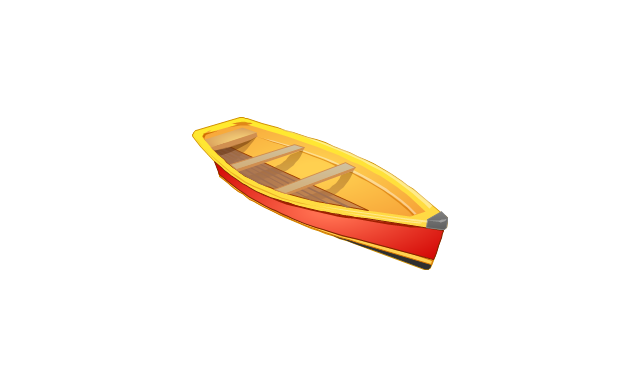
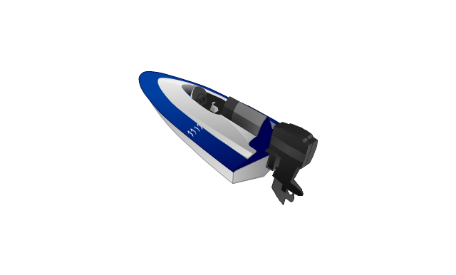
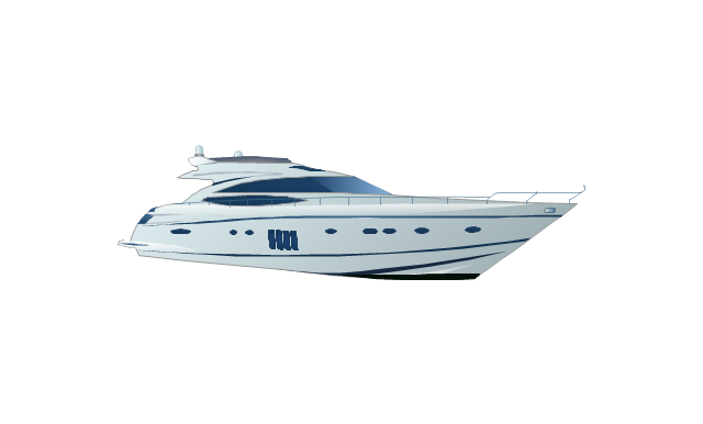
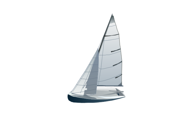
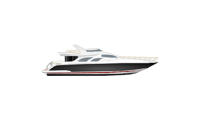
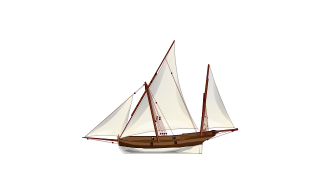
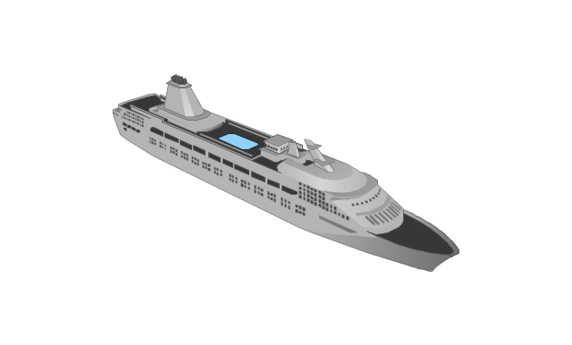
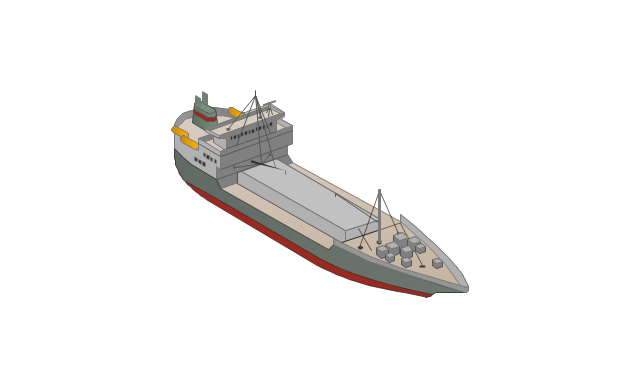
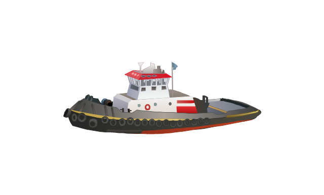
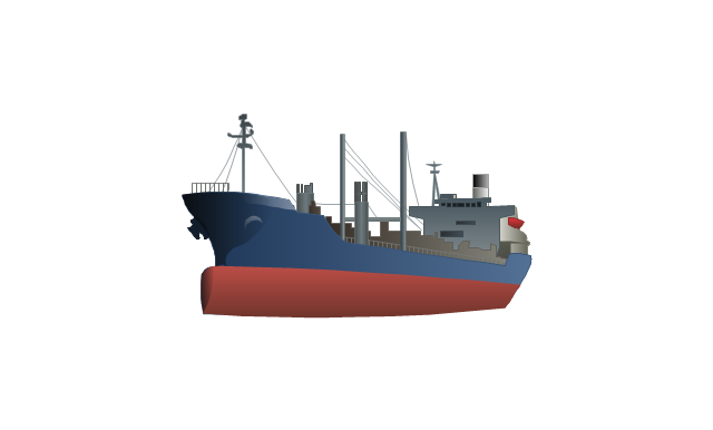
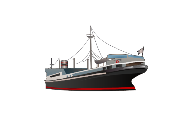
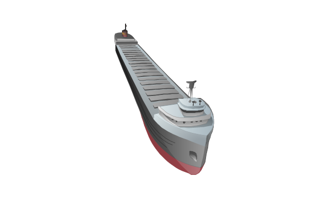
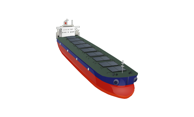
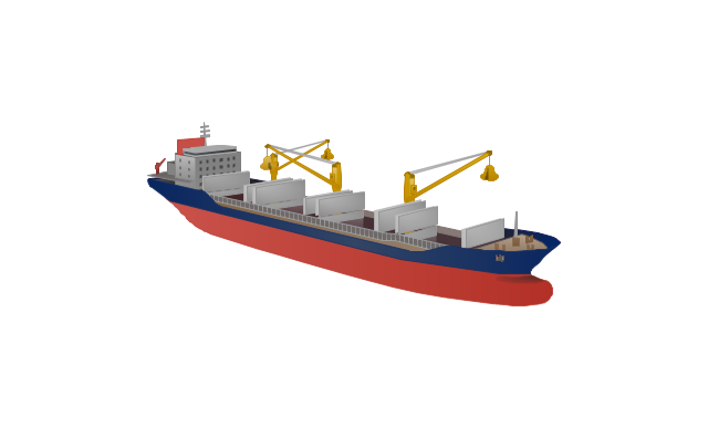
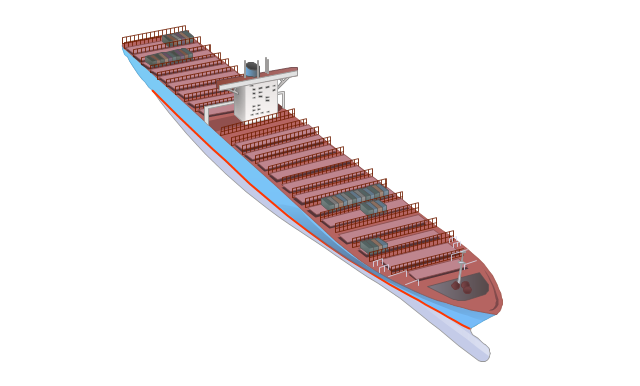
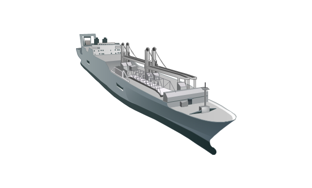
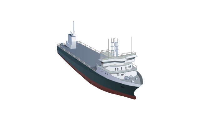
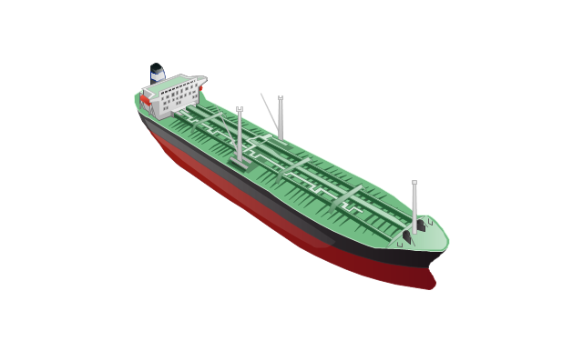
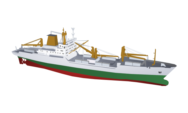
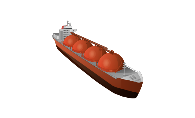
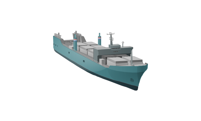
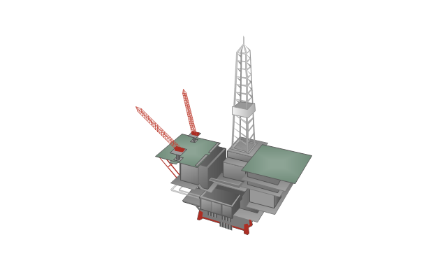
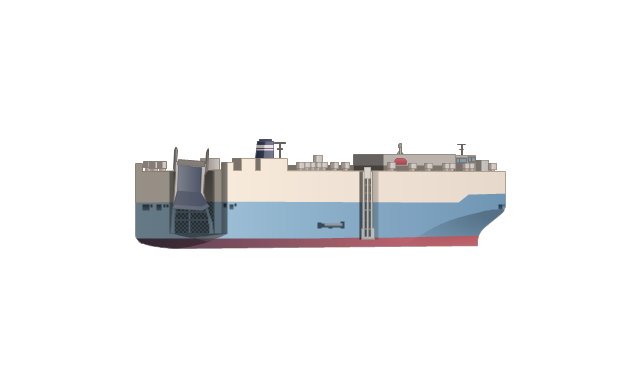
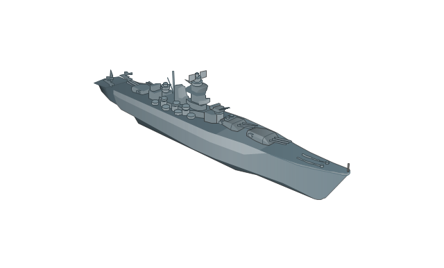
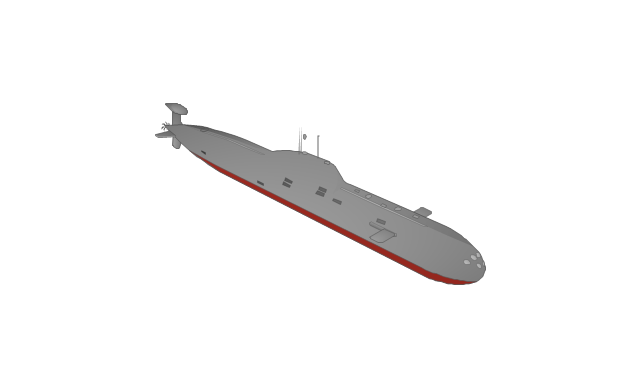
The vector stencils library "Watercraft" contains 28 clip art images for creating ship transport illustrations, presentation slides, infographics and webpages using the ConceptDraw PRO diagramming and vector drawing software.
"The term watercraft covers a range of different vehicles including ships, boats, hovercraft and submarines, and differs from a simple device that merely floats, such as a log raft. ...
Usually the purposes behind watercraft designs and skills are for seafaring education or leisure activities, fishing and resource extraction, transportation of cargo or passengers, and for conducting combat or salvage operations. In general, the purpose of a water vehicle identifies its utility with a maritime industry sub-sector." [Watercraft. Wikipedia]
The vector stencils library "Watercraft" is included in the Aerospace and Transport solution from the Illustrations area of ConceptDraw Solution Park.
www.conceptdraw.com/ solution-park/ illustrations-aerospace-transport
The vector stencils library "Pumps" contains 82 symbols of pumps, compressors, fans, turbines, and power generators.
Use these icons to design pumping systems, air and fluid compression systems, and industrial process diagrams.
"A pump is a device that moves fluids (liquids or gases), or sometimes slurries, by mechanical action. Pumps can be classified into three major groups according to the method they use to move the fluid: direct lift, displacement, and gravity pumps.
Pumps operate by some mechanism (typically reciprocating or rotary), and consume energy to perform mechanical work by moving the fluid. Pumps operate via many energy sources, including manual operation, electricity, engines, or wind power, come in many sizes, from microscopic for use in medical applications to large industrial pumps.
Mechanical pumps serve in a wide range of applications such as pumping water from wells, aquarium filtering, pond filtering and aeration, in the car industry for water-cooling and fuel injection, in the energy industry for pumping oil and natural gas or for operating cooling towers. In the medical industry, pumps are used for biochemical processes in developing and manufacturing medicine, and as artificial replacements for body parts, in particular the artificial heart and penile prosthesis.
In biology, many different types of chemical and bio-mechanical pumps have evolved, and biomimicry is sometimes used in developing new types of mechanical pumps." [Pump. Wikipedia]
The example "Design elements - Pumps" was created using the ConceptDraw PRO diagramming and vector drawing software extended with the Chemical and Process Engineering solution from the Engineering area of ConceptDraw Solution Park.
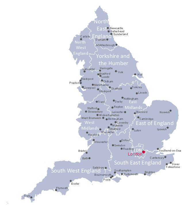
This political map example shows English regions, cities and towns.
"England is a country that is part of the United Kingdom. It shares land borders with Scotland to the north and Wales to the west. The Irish Sea lies northwest of England and the Celtic Sea lies to the southwest. England is separated from continental Europe by the North Sea to the east and the English Channel to the south. The country covers much of the central and southern part of the island of Great Britain, which lies in the North Atlantic; and includes over 100 smaller islands such as the Isles of Scilly, and the Isle of Wight. ...
The subdivisions of England consist of up to four levels of subnational division controlled through a variety of types of administrative entities created for the purposes of local government. The highest tier of local government were the nine regions of England: North East, North West, Yorkshire and the Humber, East Midlands, West Midlands, East, South East, South West, and London. ...
There are fifty settlements which have been designated city status in England, while the wider United Kingdom has sixty-six.
While many cities in England are quite large in size, such as Birmingham, Sheffield, Manchester, Liverpool, Leeds, Newcastle, Bradford, Nottingham and others, a large population is not necessarily a prerequisite for a settlement to be afforded city status. Traditionally the status was afforded to towns with diocesan cathedrals and so there are smaller cities like Wells, Ely, Ripon, Truro and Chichester." [England. Wikipedia]
The political map example "English cities and towns map" was drawn using ConceptDraw PRO software extended with the Map of UK solution from the Maps area of ConceptDraw Solution Park.
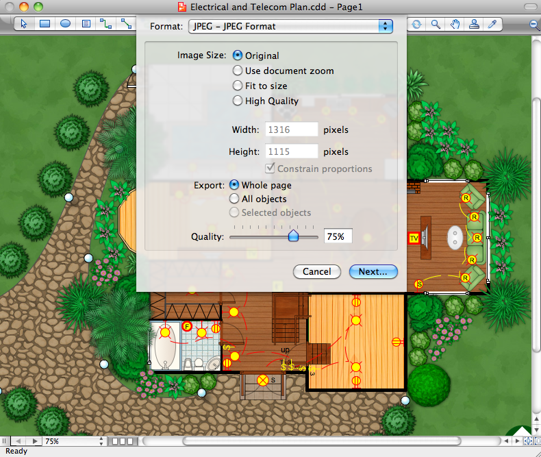
Building Plans with ConceptDraw DIAGRAM
If it is necessary for you to create the building plan you can draw it manually on the sheet of paper, but also you can use special software. With the help of ConceptDraw you can create the building plan of any difficulty. Thanks to special templates and objects libraries this won't take you much time and won't demand special skills.Technical Flow Chart
Flow chart is a diagrammatic representation of an algorithm and essential part of planning the system. Flow charts are widely used in technical analysis and programming for easy writing programs and explaining them to others. So, one of the most popular type of flow charts is Technical Flow Chart. Technical Flow Chart can be drawn by pencil on the paper, but it will be easier to use for designing a special software. ConceptDraw DIAGRAM diagramming and vector drawing software extended with Flowcharts Solution from the "Diagrams" Area of ConceptDraw Solution Park will be useful for this goal.Work Order Process Flowchart. Business Process Mapping Examples
The business process is a set of actions or tasks which are undertaken by an organization for production some goods or services, they are then offered for the customers and are ordered by them. Process Flowcharts and Order Process Flowcharts are sufficiently prevalent, well known and actively used in variety of fields of life, business and science. They are constructed using the common standardized symbols, thus are clear and understandable for all. They help effectively represent the processes, determine the order in which the process activities happen, document the order processes, and also effectively analyze the processes with a goal to increase their efficiency. Create your own Process Flowcharts, Order Process Flowcharts, Cross-Functional Flow Charts representing the order processing steps using powerful drawing tools of ConceptDraw DIAGRAM software and variety of predesigned vector objects from the libraries of Business Process Mapping Solution from Business Processes area of ConceptDraw Solution Park.- Natural gas condensate - PFD | Formation Of Petroleum And Natural ...
- Natural gas condensate - PFD | Process Flow Diagram Symbols ...
- Natural gas condensate - PFD | Amine treating unit schematic ...
- Chemistry Drawings | Natural gas condensate - PFD | Gravity ...
- Natural gas condensate - PFD | Types of Flowcharts | Process Flow ...
- Natural gas condensate - PFD | Chemistry | Chemistry Symbols and ...
- Watercraft - Vector stencils library
- Natural gas condensate - PFD | Process Flow Diagram | Process ...
- Natural gas condensate - PFD | Global natural gas consumption ...
- Process Flow Diagram Oil And Gas Production
- Process Flowchart | Process Flow Diagram Symbols | Process flow ...
- Process flow diagram - Typical oil refinery
- Design elements - Chemical engineering | Crude oil distillation unit ...
- Crude oil distillation unit - PFD | Process Engineering | Chemical ...
- Process flow diagram - Typical oil refinery | Crude oil distillation unit ...
- Process flow diagram - Typical oil refinery | Chemical and Process ...
- Drawing a Nature Scene | Drawing Illustration | Beauty in nature ...
- Drawing Illustration | Process Diagrams | Bar Diagram Math ...
- Plumbing and Piping Plans | Building Drawing Design Element ...
-natural-gas-condensate---pfd.png--diagram-flowchart-example.png)
