UML Block Diagram

The Building Blocks Used in EPC Diagrams
")
About UML

Class Diagram Tool

 Rapid UML
Rapid UML solution extends ConceptDraw PRO software with templates, samples and libraries of vector stencils for quick drawing the UML diagrams using Rapid Draw technology.
 Event-driven Process Chain Diagrams
Event-driven Process Chain (EPC) Diagram is a type of flowchart widely used for modeling in business engineering and reengineering, business process improvement, and analysis. EPC method was developed within the Architecture of Integrated Information Systems (ARIS) framework.
 Rapid UML
Rapid UML solution extends ConceptDraw PRO software with templates, samples and libraries of vector stencils for quick drawing the UML diagrams using Rapid Draw technology.
 Block Diagrams
Block diagrams solution extends ConceptDraw PRO software with templates, samples and libraries of vector stencils for drawing the block diagrams.
 Pyramid Diagrams
Pyramid Diagrams solution extends ConceptDraw PRO software with templates, samples and library of vector stencils for drawing the marketing pyramid diagrams.
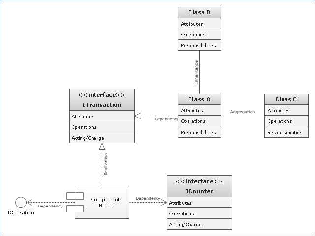
"In software engineering, a class diagram in the Unified Modeling Language (UML) is a type of static structure diagram that describes the structure of a system by showing the system's classes, their attributes, operations (or methods), and the relationships among objects. ...
The class diagram is the main building block of object oriented modelling. It is used both for general conceptual modelling of the systematics of the application, and for detailed modelling translating the models into programming code. Class diagrams can also be used for data modeling. The classes in a class diagram represent both the main objects, interactions in the application and the classes to be programmed." [Class diagram. Wikipedia]
The template "UML class diagram" for the ConceptDraw PRO diagramming and vector drawing software is included in the Rapid UML solution from the Software Development area of ConceptDraw Solution Park.
www.conceptdraw.com/ solution-park/ software-uml
UML class diagram
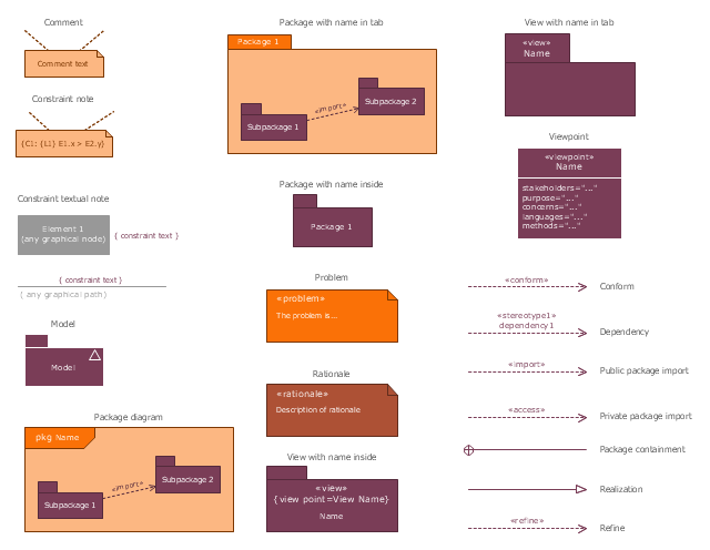
UML Package Diagram. Design Elements

UML Class Diagram Notation

UML Activity Diagram

UML Collaboration Diagram (UML2.0)


The vector stencils library "SysML diagrams" contains 19 symbols.
Use it to design your SysML diagrams using ConceptDraw PRO diagramming and vector drawing software.
"The Systems Modeling Language (SysML) is a general-purpose modeling language for systems engineering applications. It supports the specification, analysis, design, verification and validation of a broad range of systems and systems-of-systems.
SysML was originally developed by an open source specification project, and includes an open source license for distribution and use. SysML is defined as an extension of a subset of the Unified Modeling Language (UML) using UML's profile mechanism." [Systems Modeling Language. Wikipedia]
The building blocks example "Design elements - SysML diagrams" is included in the SysML solution from the Software Development area of ConceptDraw Solution Park.
SysML diagram building blocks
- UML Block Diagram | About UML | The Building Blocks Used in EPC ...
- UML Block Diagram
- UML Block Diagram | The Building Blocks Used in EPC Diagrams ...
- UML Block Diagram | About UML | The Building Blocks Used in EPC ...
- UML Block Diagram | Office Layout Plans | The Building Blocks ...
- UML Block Diagram | Building Drawing Design Element: Plumbing ...
- UML Block Diagram | UML Collaboration Diagram. Design Elements ...
- Major Building Block Uml
- What Is Relationship In Uml Building Blocks In Software Engineering
- Flow chart Example. Warehouse Flowchart | UML Block Diagram ...
- UML Block Diagram | UML Use Case Diagram Example. Services ...
- Diagramming Software for designing UML Sequence Diagrams ...
- UML Class Diagram Example - Buildings and Rooms | Sales ...
- Building Project Diagram
- Uml Is A General Purpose Modeling Language In The Field Of
- Building Block Diagrams Of Computer
- UML Block Diagram | Building Drawing Software for Design ...
- UML Block Diagram | Basic Diagramming | Functional Block ...
- The Building Blocks Used in EPC Diagrams | Work Order Process ...
- Sales Process Flowchart. Flowchart Examples | UML Use Case ...