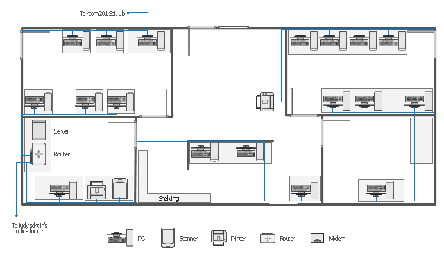
This network layout floorplan example was drawn on the base of the picture "Ethernet cable layout" illustrating "UGA Technical Network Liaison Handbook" from the website of the University of Georgia.
[netinfo.uga.edu/ tnlhand/ landiag.gif]
"The Ethernet physical layer is the physical layer component of the Ethernet family of computer network standards.
The Ethernet physical layer evolved over a considerable time span and encompasses quite a few physical media interfaces and several magnitudes of speed. The speed ranges from 1 Mbit/ s to 100 Gbit/ s, while the physical medium can range from bulky coaxial cable to twisted pair and optical fiber. In general, network protocol stack software will work similarly on all physical layers.
10-gigabit Ethernet was already used in both enterprise and carrier networks by 2007, with 40 Gbit/ s and 100 Gbit/ s Ethernet ratified." [Ethernet physical layer. Wikipedia]
The network layout floorplan example "Ethernet cable layout" was created using the ConceptDraw PRO diagramming and vector drawing software extended with the Network Layout Floor Plans solution from the Computer and Networks area of ConceptDraw Solution Park.
Basic Network Diagram
The Basic Network Diagram is an easy and effective way to design and document a simple network, it lets to represent visually and logically how the different network devices and computer equipment can be installed to meet the main business needs. ConceptDraw DIAGRAM software supplied with Computer Network Diagrams solution from the Computer and Networks area of ConceptDraw Solution Park is a perfect tool for drawing the Basic Computer Network diagrams, designs, schematics, and maps, network architectures, topologies, and layouts. Numerous vector libraries of network symbols, icons and components are incredibly helpful for IT and telecom engineers, stakeholders and end-users when designing Basic Network Diagrams, Common Network Diagrams, Common Network Topologies, 10Base-T Star Network Topologies, Bus Topology Diagrams, Communication Network Diagrams, System Designs, Regional Cable Head-End Diagrams, etc. Collection of predesigned samples and templates included to Computer Network Diagrams solution also greatly extends the capabilities of ConceptDraw DIAGRAM users.
- Cable Network . Computer and Network Examples | Network ...
- Network Layout Floor Plans | Ethernet cable layout | Ethernet local ...
- Ethernet cable layout | Network wiring cable. Computer and Network ...
- Network Cable Diagram For Wires
- Cable Network . Computer and Network Examples | Network wiring ...
- Local area network ( LAN ). Computer and Network Examples ...
- Call shop solution | Network wiring cable . Computer and Network ...
- Network wiring cable . Computer and Network Examples | Local area ...
- ConceptDraw PRO Network Diagram Tool | Network Layout Floor ...
- Network wiring cable . Computer and Network Examples | Local area ...
- Cable Network . Computer and Network Examples | Network wiring ...
- Network Cable Management Design
- Network wiring cable . Computer and Network Examples | Network ...
- Ethernet Cable Diagram For Computer
- Network wiring cable . Computer and Network Examples | Draw ...
- Cable Layout Diagram Sample
- Network Layout Floor Plans | Design elements - Network layout ...
- Network Cable Diagram
- Telecommunication networks . Computer and Network Examples ...
- Network wiring cable . Computer and Network Examples

