Data Flow Diagram (DFD)
A Data Flow Diagram (DFD) illustrates the flow of data through an information system, visualizes how the information is handled in terms of inputs and outputs, how the data enter to system and leave it. It is effective to use a Data Flow Diagram for creation the system's overview, to show the system's scope and boundaries. There are two different types of notations for DFDs: Yourdon-Coad and Gane-Sarson, which differ in visual representations for processes, data flow, data stores, external entities, etc. Thus, for example the processes are depicted as circles in Yourdon-Coad notation and as rounded squares in Gane-Sarson notation. Gane-Sarson notation is usually used for visualization information systems and Yourdon-Coad - for system analysis and design. The Data Flow Diagrams solution included to Software Development area of ConceptDraw Solution Park offers a lot of DFD templates, samples and examples, libraries of vector stencils for construction without efforts the DFDs according to both Gane-Sarson and Yourdon-Coad notations.DFD Library System
The Data Flow Diagram (DFD) is a graphical technique used for effective modeling and analyzing the information processes and systems. Having at the disposal the DFD library system and newest powerful tools of ConceptDraw DIAGRAM diagramming and vector drawing software supplied with Data Flow Diagrams (DFD) solution from the Software Development area of ConceptDraw Solution Park, you can design fast and easy the Data flow diagrams, Data flowcharts, Data flow models, Data flow process diagrams, Process-oriented models, Data-oriented models, Data process diagrams, Structured analysis diagrams, Information flow diagrams of any type and complexity. For designing the Data Flow Diagrams in ConceptDraw DIAGRAM software are used the simple DFD flowchart symbols from the offered DFD libraries - Data Flow Diagram (DFD) library, Yourdon and Coad Notation library, and Gane-Sarson Notation library. The DFD objects are need to be connected each other by the arrows to depict the data flow from one step to another, that you can do in seconds in ConceptDraw DIAGRAM , as well as set desired design of your diagram.Business Processes description with ConceptDraw DIAGRAM
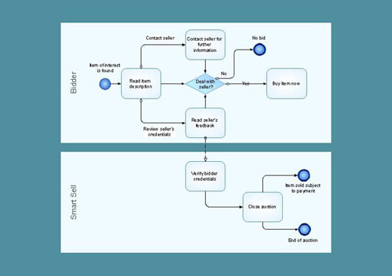
Business Processes description with ConceptDraw. Business-processes it allows to describe functional blocks, for example production and marketing. ConceptDraw lets creation of business processes description using IDEF0 and IDEF2 methods.- Explain The Function And Purpose Of Each And Every Stage Of The ...
- Systems development life cycle | Structured Systems Analysis and ...
- Systems development life cycle | SSADM Diagram | Structured ...
- Systems development life cycle | Circular Flow Diagram Template ...
- Data Flow Diagram Example In Sdlc Phases
- Sample Flow Charts In System Development Life Cycle
- Systems development life cycle | SSADM Diagram | Circular Arrows ...
- Systems development life cycle | SSADM Diagram | Circular Flow ...
- Systems development life cycle | SSADM Diagram | Circular Arrows ...
- Systems development life cycle | SSADM Diagram | Circular Flow ...
- Structured Systems Analysis and Design Method ( SSADM ) with ...
- Innovation life cycle - Arrow loop diagram | Draw Flowcharts with ...
- Systems development life cycle | Process Flowchart | JSD - Jackson ...
- Examples Of System Development Life Cycle Flow Chart
- Systems development life cycle | Circular Flow Diagram Template ...
- Draw Diagram Of Information System Development Cycle
- Software Development Life Cycle Phases Diagram Of Data Flow
- Process Flowchart | Systems development life cycle | JSD - Jackson ...
- Innovation life cycle - Arrow loop diagram | BPM life cycle | Systems ...
- Systems development life cycle | Life cycle of an ASAM standard ...


