 Mechanical Engineering
This solution extends ConceptDraw DIAGRAM.9 mechanical drawing software (or later) with samples of mechanical drawing symbols, templates and libraries of design elements, for help when drafting mechanical engineering drawings, or parts, assembly, pneumatic,
HelpDesk
How to Create a Mechanical Diagram

Making Mechanical Diagram

Technical Drawing Software

Technical Drawing Software

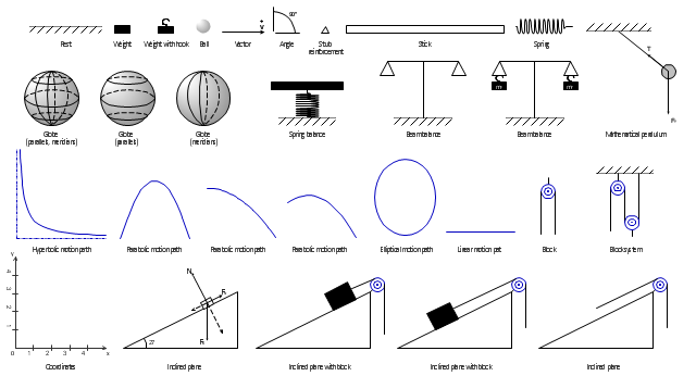
The vector stencils library "Mechanics" contains 29 symbol shapes for drawing mechanics experiment schemes and physical diagrams.
"Mechanics ... is the branch of science concerned with the behavior of physical bodies when subjected to forces or displacements, and the subsequent effects of the bodies on their environment. The scientific discipline has its origins in Ancient Greece with the writings of Aristotle and Archimedes. During the early modern period, scientists such as Galileo, Kepler, and especially Newton, laid the foundation for what is now known as classical mechanics. It is a branch of classical physics that deals with particles that are either at rest or are moving with velocities significantly less than the speed of light. It can also be defined as a branch of science which deals with the motion of and forces on objects." [Mechanics. Wikipedia]
The example "Design elements - Mechanics" was created using the ConceptDraw PRO diagramming and vector drawing software extended with the Physics solution from the Science and Education area of ConceptDraw Solution Park.
Mechanical symbols
 Engineering
This solution extends ConceptDraw DIAGRAM.4 with the ability to visualize industrial systems in electronics, electrical, chemical, process, and mechanical engineering.
 ConceptDraw Solution Park
ConceptDraw Solution Park collects graphic extensions, examples and learning materials
CAD Drawing Software for Making Mechanic Diagram and Electrical Diagram Architectural Designs


Process Flow Diagram Symbols

Flow Diagram Software

HelpDesk
How to Draw Physics Diagrams

The vector stencils library "Dimensioning and tolerancing" contains 45 symbols of geometric dimensions and mechanical tolerances, geometric symbols, callouts, and text boxes and inserts.
Use these geometric dimensioning and tolerancing (GD&T) shapes to create annotated mechanical drawings.
"Geometric dimensioning and tolerancing (GD&T) is a system for defining and communicating engineering tolerances. It uses a symbolic language on engineering drawings and computer-generated three-dimensional solid models that explicitly describes nominal geometry and its allowable variation. It tells the manufacturing staff and machines what degree of accuracy and precision is needed on each controlled feature of the part. GD&T is used to define the nominal (theoretically perfect) geometry of parts and assemblies, to define the allowable variation in form and possible size of individual features, and to define the allowable variation between features." [Geometric dimensioning and tolerancing. Wikipedia]
The shapes example "Design elements - Dimensioning and tolerancing" was created using the ConceptDraw PRO diagramming and vector drawing software extended with the Mechanical Engineering solution from the ConceptDraw Solution Park.
Dimensioning and tolerancing symbols

Block Diagram Creator

Electrical Symbols — Terminals and Connectors

- Technical Drawing Software | Making Mechanical Diagram ...
- Mechanical Drawing Symbols | Mechanical Drawing Software ...
- Mechanical Engine Component Drawings
- Mechanical Drawing Symbols | Design elements - Bearings ...
- Mechanical Flow Diagram
- Mechanical Drawing Symbols | Basic Flowchart Symbols and ...
- How To Draw A Mechanical Engineering Schematics
- Mechanical Drawing Symbols | Mechanical Engineering ...
- Mechanical Engineering | Engineering | How to Create a ...
- Design elements - Bearings | Mechanical Drawing Symbols ...
- SSADM Diagram | Mechanical Engineering | What Is Scrum In Testing
- Process Flowchart | Mechanical Drawing Symbols | Mechanical ...
- How to Create a Mechanical Diagram | Mechanical Engineering ...
- Technical drawing - Machine parts assembling | Mechanical ...
- Mechanical Drawing Symbols | Mechanical Engineering | Process ...
- Mechanical Drawing Symbols | Mechanical Design Software ...
- Making Mechanical Diagram | Mechanical Engineering | How to ...
- Mechanical Drawing Symbols | Process Flowchart | CAD Drawing ...
- How to Create a Mechanical Diagram | How to Draw Physics ...
- Elements location of a welding symbol | Mechanical Engineering ...