"Logical topology, or signal topology, is the arrangement of devices on a computer network and how they communicate with one another. How devices are connected to the network through the actual cables that transmit data, or the physical structure of the network, is called the physical topology. Physical topology defines how the systems are physically connected. It represents the physical layout of the devices on the network. The logical topology defines how the systems communicate across the physical topologies.
Logical topologies are bound to network protocols and describe how data is moved across the network. ...
EXAMPLE : twisted pair Ethernet is a logical bus topology in a physical star topology layout. while IBM's token ring is a logical ring topology, it is physically set up in star topology." [Logical topology. Wikipedia]
This Cisco logical computer network diagram example was created using the ConceptDraw PRO diagramming and vector drawing software extended with the Cisco Network Diagrams solution from the Computer and Networks area of ConceptDraw Solution Park.
HelpDesk
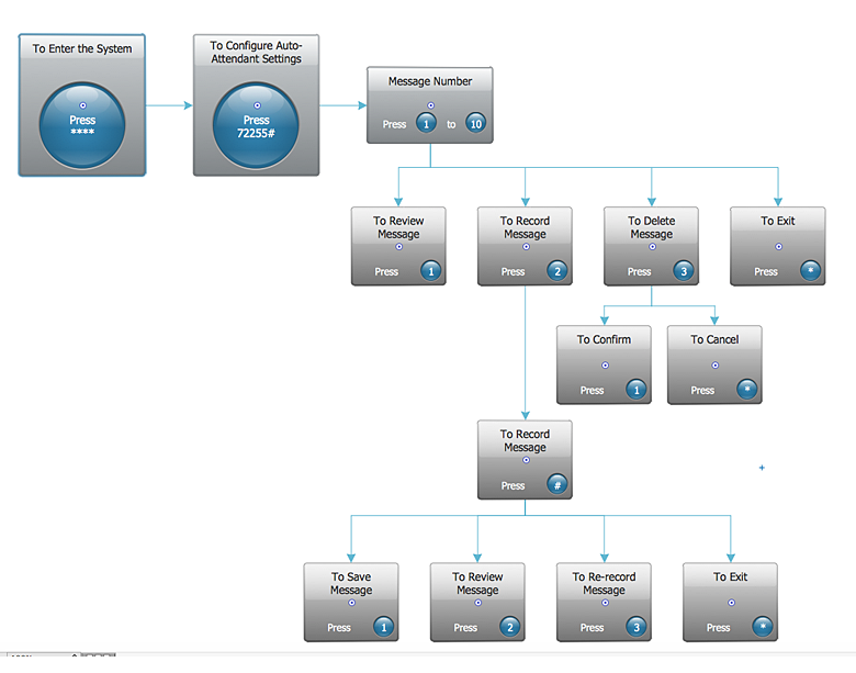
How to Create an Interactive Voice Response (IVR) Diagram in ConceptDraw PRO
Interactive Voice Response (IVR) Diagram is used to create and conduct the Interactive Voice Response systems for call-centers and voice mail services. IVR diagrams intended to visualize the logical and physical structure of Interactive voice response systems. ConceptDraw solution for Interactive Voice Response (IVR) Diagram allows you to create and communicate the Interactive Voice Response diagram of any complexity. Interactive Voice Response (IVR) System is a telecommunication technology that enables a computer to automatically process voice and touch phone signals. IVR systems allows users to interact through a computer with various service systems, available by telephone. The objective of IVR system is to reduce customer service costs by delivering self service to customers and guiding them to the information that they look for.- Network topologies diagram | Network Topology | Cisco Network ...
- Tree Network Topology Diagram | Network Topologies | Star ...
- Network Diagram Examples | Bus network topology diagram | Basic ...
- Diagram Physical Topologies | Hotel Network Topology Diagram ...
- Wireless Network Topology | Hotel Network Topology Diagram ...
- Complete Network Topology | Fully Connected Network Topology ...
- Hotel Network Topology Diagram . Hotel Guesthouse WiFi Network ...
- Star Network Topology | Hotel Network Topology Diagram | Tree ...
- Cisco Network Topology . Cisco icons, shapes, stencils and symbols ...
- Network Topology | Cisco Network Topology | Hotel Network ...
- Physical LAN and WAN diagram template
- Local Area Network Diagram
- Home Area Network Example
- How To Draw Building Plans | Network Diagram Examples | Network ...
- Network Diagram Examples | Network Architecture | Wireless ...
- Computer network system design diagram | Network Diagramming ...
- Satellite network diagram | Network diagrams with ConceptDraw ...
- Draw The Diagram Of Topology
- Satellite network diagram | Hybrid satellite and common carrier ...
- Local Area Network With Digram

