HelpDesk
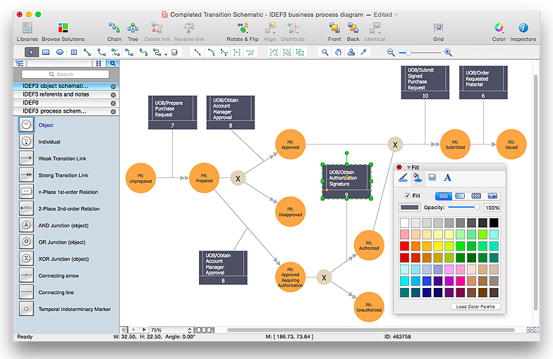
How to create an IDEF3 diagram using ConceptDraw PRO
IDEF3 is a member of the IDEF family of modeling methods that can be used to describe operations in a business process. An IDEF3 diagram provides a description of actual process flow within an organization or business, or the changes that occur to an object within that system. This method of knowledge capture is recorded in two different perspectives - users are able to create both process schematics and object schematics using the IDEF3 schematic symbols. ConceptDraw has created a solution that collects all symbols necessary to create professional IDEF3 diagrams. IDEF methodology is suitable for almost any form of business, and for anyone who needs to record enterprise architecture in a process driven manner. The IDEF Business Process Diagram solution and ConceptDraw PRO cater for these needs, giving both beginner and experienced users the tools they need to create effective business process diagrams.HelpDesk
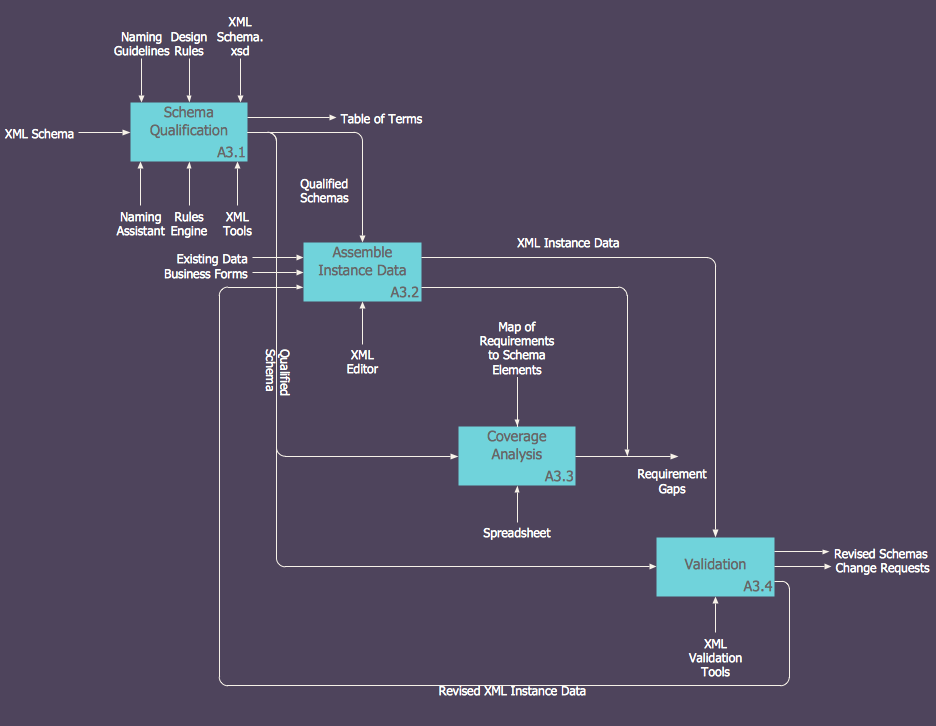
How to Create an IDEF0 Diagram for an Application Development
IDEF0 methods are intended to model the functions of a process, creating a graphical model that displays: what controls the function, who makes it, what resources are used and how they are connected with other functions. The IDEF0 tool is used to model the decisions, actions, and activities of a software system during the development process . IDEF0 diagram graphically depicts a model of a desired version of the application. ConceptDraw PRO allows you to create and communicate the IDEF0 diagrams of any complexity.HelpDesk
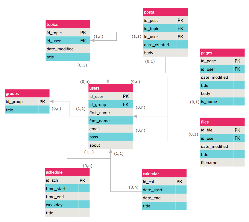
How to Create an ERD Diagram
ERD (entity relationship diagram) is used to show the logical structure of databases. It represents the interrelationships between components of database (entities). Entity relationship diagrams are a widely used in software engineering. Using ERD software engineers can control the every aspect of database development. ER diagram can be used as guide for testing and communicating before the release of software product. ERD displays data as entities that are connected with connections that show the relationships between entities. There is some ERD notations used by data bases developers for representing the relationships between the data objects. ConceptDraw PRO and its ERD solution allow you to build ERD diagram of any notation.HelpDesk
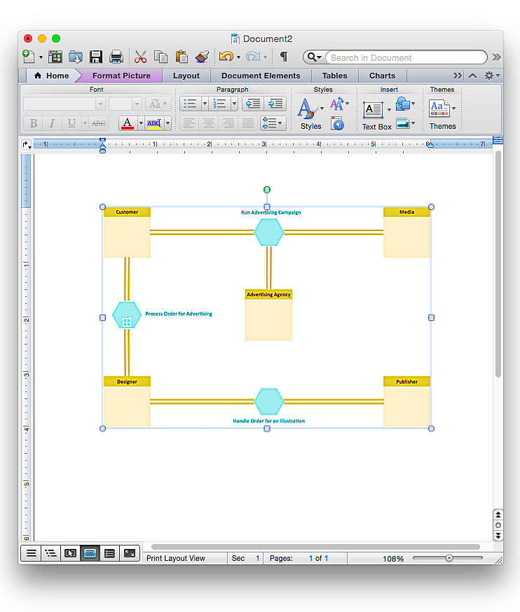
How to Add a Business Process Diagram to a MS Word Document Using ConceptDraw PRO
ConceptDraw PRO allows you to easily create business process diagrams and then add them to a MS Word document.- Data Flow Diagram Symbols . DFD Library | Entity Relationship ...
- Basic Flowchart Symbols and Meaning | Flowchart design ...
- Entity Relationship Diagram Symbols and Meaning ERD Symbols ...
- Data Flow Diagram Symbols . DFD Library | Basic Flowchart ...
- ERD Symbols and Meanings | Entity Relationship Diagram Symbols ...
- Business Process Diagram | Process Flowchart | Business Process ...
- Process Flowchart | Business Process Modeling Notation Template ...
- Basic Flowchart Symbols and Meaning | Process Flowchart ...
- Gane Sarson Diagram | Data Flow Diagram Process | Data flow ...
- Business Process Diagram | Process Flowchart | Cross-Functional ...
- Basic Flowchart Symbols | Flow Chart Symbols | Process Flowchart ...
- Booking Process Flow Chart
- Process Flowchart | Structured Systems Analysis and Design ...
- Business Process Modeling Software for Mac | Flow Diagram ...
- Data Flow Diagrams | Process Flowchart | Visio Files and ...
- Entity Relationship Diagram Software for Design Crows Foot ER ...
- Cross-Functional Flowchart (Swim Lanes) | Swim Lane Diagrams ...
- Business Process Modeling Notation Template | Workflow Diagram ...
- Design elements - ERD (crow's foot notation ) | Entity Relationship ...


