Electrical Symbols, Electrical Diagram Symbols

How To use House Electrical Plan Software


Local area network (LAN). Computer and Network Examples
 diagram")

Wiring Diagram Floor Software
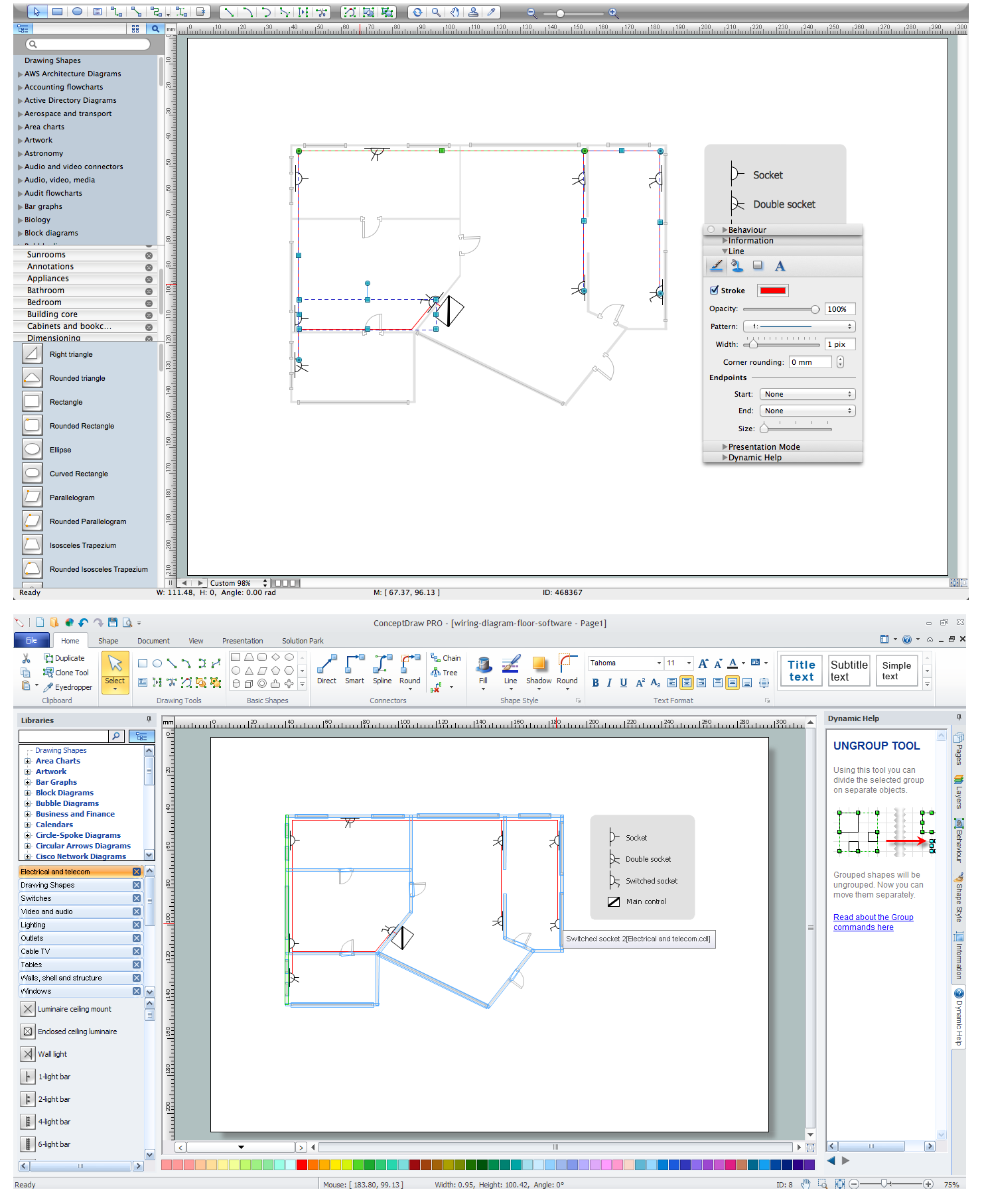
Home Electrical Plan

Electrical and Telecom Plan Software

CAD Drawing Software for Making Mechanic Diagram and Electrical Diagram Architectural Designs

Wiring Diagrams with ConceptDraw DIAGRAM

HelpDesk
How to Create a CCTV Diagram

HelpDesk
How to Create an Electrical Diagram

- Electrical Building Installation Layout And Wiring Diagram In Pdf
- Building Electrical Installation Design Pdf
- Plumbing and Piping Plans | 2bedroom House Wiring Diagram Pdf
- Layout And Wiring Diagram For Residential Building In Pdf
- Examples For Schematic Diagram For Residential Building
- House Wiring Diagram Pdf
- Commercial Building Wiring Diagram
- How To Draw Riser Diagram Of Sanitary Building With Example Pdf
- Commercial Building Electrical Wiring Plan
- Wiring Layout For Residential Building