Types of Flowcharts


Technical Flow Chart

Process Flowchart


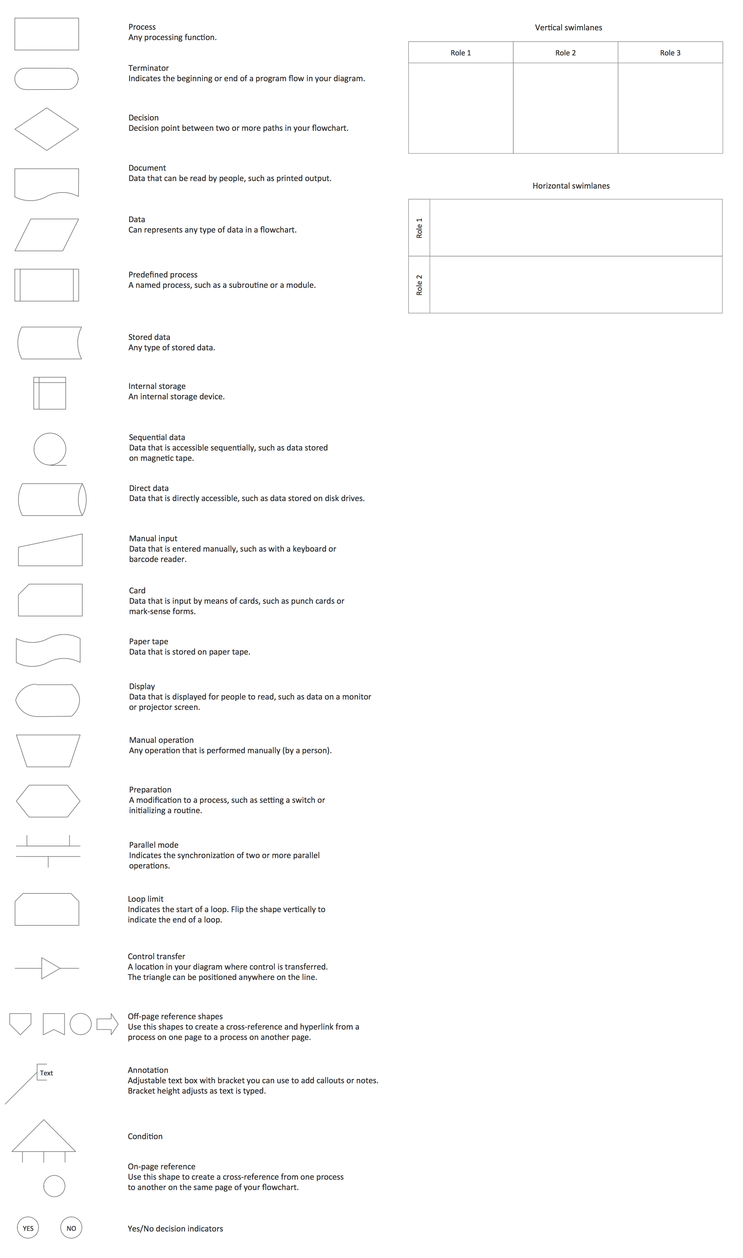
Business Process Flowchart Symbols

Flowchart Definition

Flowchart
Cross-Functional Flowchart


Data Flow Diagram Model

Cross Functional Flowchart Symbols
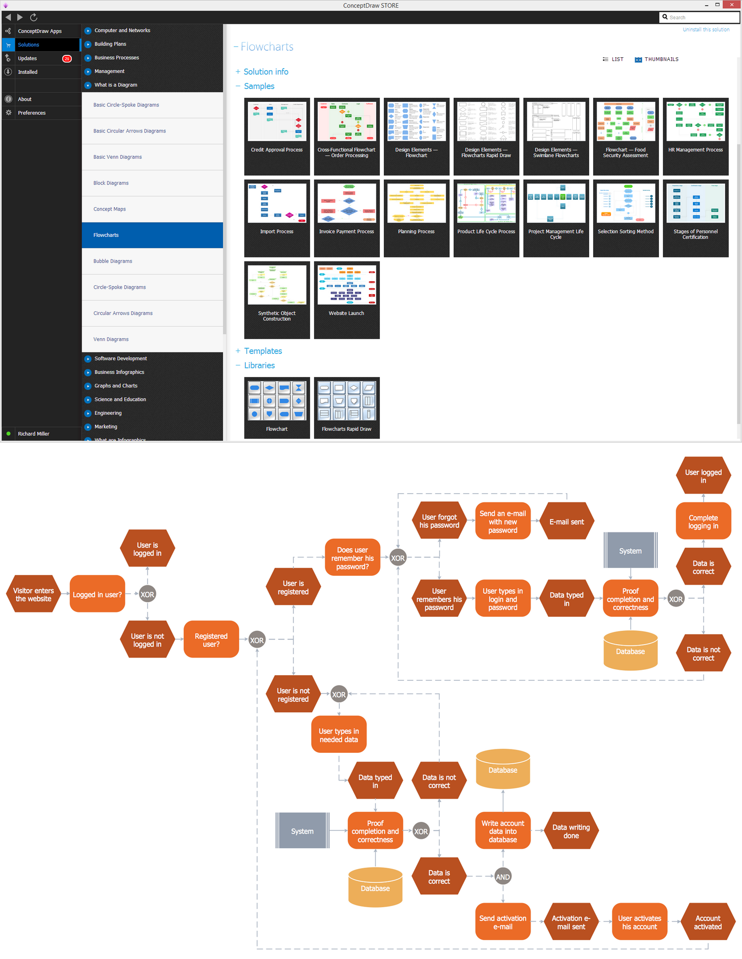
Processing Flow Chart

ConceptDraw DIAGRAM enhanced with Flowcharts Solution from the "Diagrams" Area of ConceptDraw Solution Park is a powerful Processing Flow Chart software which will help save lots of your time.
- Basic Flowchart Symbols and Meaning | Flowchart Programming ...
- Draw A Flowchart On How To Prepare For Examination
- Process Flowchart | Flowchart Marketing Process . Flowchart ...
- Activity Network (PERT) Chart | Activity Network Diagram Method ...
- Flow chart Example. Warehouse Flowchart | Basic Flowchart ...
- Business Process Flowchart Symbols | Basic Flowchart Symbols ...
- Process Flowchart | Basic Flowchart Symbols and Meaning ...
- Flow chart Example. Warehouse Flowchart | Basic Flowchart ...
- Flow Chart Symbols | Gant Chart in Project Management | How to ...
- Basic Flowchart Symbols and Meaning | Business feedback loop ...