Data structure diagram with ConceptDraw PRO
Data structure diagram (DSD) is intended for description of conceptual models of data (concepts and connections between them) in the graphic format for more obviousness. Data structure diagram includes entities description, connections between them and obligatory conditions and requirements which connect them. Create Data structure diagram with ConceptDraw PRO."The most common issue tracking system's design is relatively simple. A database is the main storage repository for all data. The data is managed by the business logic layer of the application. This layer gives the underlying raw data more structure and meaning, preparing it for human consumption. The now human readable data are then presented to the support technician by another software application or web page. The end-user of the issue tracking system can create entirely new issues, read existing issues, add details to existing issues, or resolve an issue. When a user of the system makes a change, the issue tracking system will record the action and who made it, so as to maintain a history of the actions taken. Each user of the system may have issues assigned to them, that is, that user is responsible for the proper resolution of that issue. This is generally presented to the user in a list format. The user may have the option of re-assigning an issue to another user, if needed. For security, an issue tracking system will authenticate its users before allowing access to the systems." [Issue tracking system. Wikipedia]
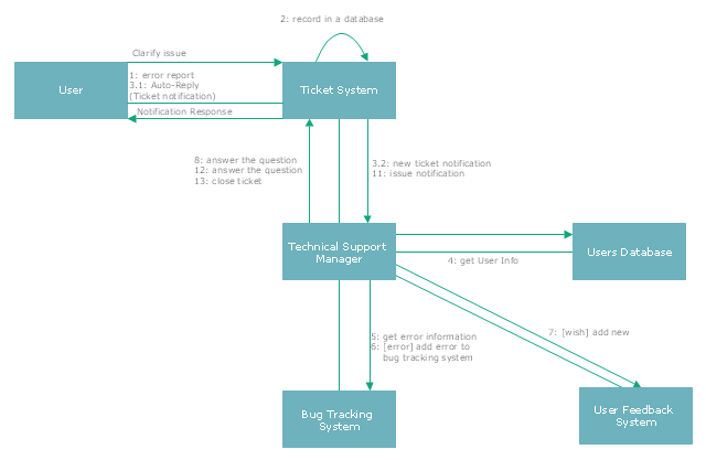
The UML communication diagram example "Ticket processing system" was created using the ConceptDraw PRO diagramming and vector drawing software extended with the Rapid UML solution from the Software Development area of ConceptDraw Solution Park.
The UML communication diagram example "Ticket processing system" was created using the ConceptDraw PRO diagramming and vector drawing software extended with the Rapid UML solution from the Software Development area of ConceptDraw Solution Park.
Network Diagrams for Bandwidth Management
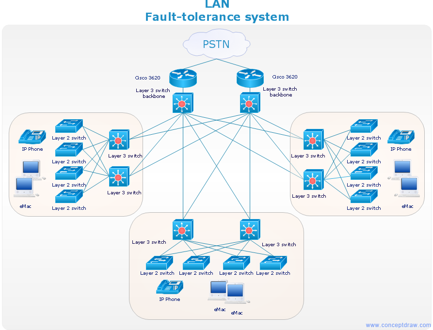
A perfect tool to draw network diagram for bandwidth management. Computer & Networks solution provides the symbol libraries with pre-designed network graphic elements. Use Computer & Networks solution to draw the network diagrams for bandwidth management for Cisco networks, Apple networks, IVR networks, GPRS networks, wi-fi networks, LAN and WAN.
- Data Communication Network With Diagram
- Block Digram Data Communications Network
- Block Diagram Of Data Communication In Networking
- Data Communication Diagram
- Satellite Communication Data Communication Diagram
- Draw And Explain The Structure Of Data Communication Network
- Process Flowchart | Data Flow Diagram | Basic Flowchart Symbols ...
- Communication network diagram
- Hotel Network Topology Diagram | Near field communication (NFC ...
- Communication medium diagram
- Types of Flowcharts | Data structure diagram with ConceptDraw ...
- Communication medium diagram | Network Diagram Examples ...
- Data Comunication Network Diagram
- Fully Connected Network Topology Diagram | Network Topologies ...
- Data Communication Architecture Diagram
- Atm Topology In Data Communication And Networking
- Organizational Structure | Communication Diagram UML2.0 ...
- Communication network diagram | Telecommunication Network ...
- Hybrid satellite and common carrier network diagram | Mobile ...
- Process Flowchart | Components of ER Diagram | Data Flow ...


