How to Create a Bank ATM Use Case Diagram
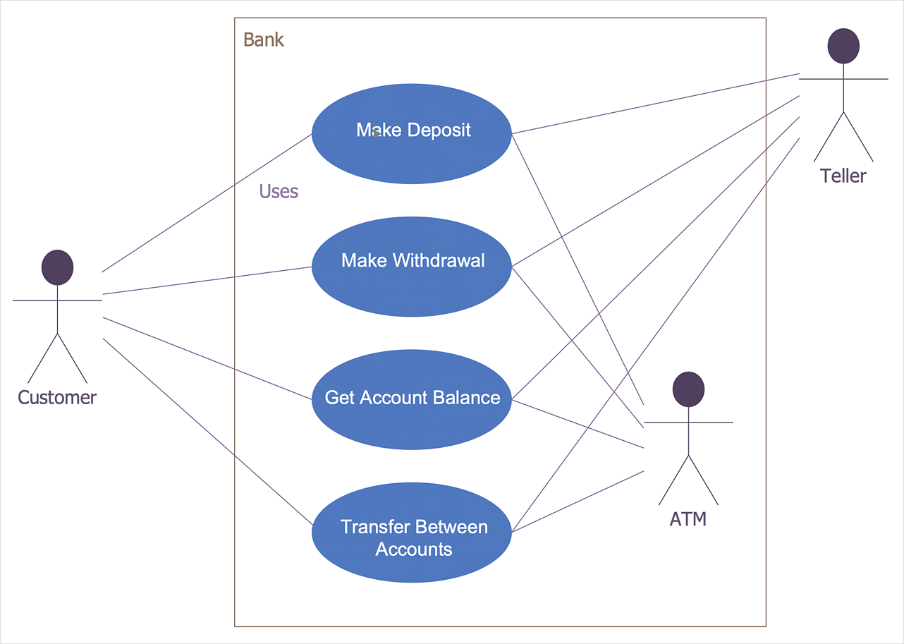
For an ATM, there are a number of different processes, transactions and interactions that can be mapped in this way using UML diagrams, or different views of the same process can be shown using different styles of the modeling language. Broadly speaking, UML diagrams are divided into two types — structural diagrams (static modeling), and behavioral diagrams (dynamic modeling). In the case of an ATM, this allows you to show the system architecture and the interaction and relationships between objects and actors (e.g., customer and bank), or the changes to these objects depending on the transaction (e.g. wrong PIN number entered). You will also need to decide if your diagram will use an object-oriented analysis (OOA) approach, or object-oriented design (OOD). The difference being that the aim of the first is to create a model of the system's functional requirements that are independent of implementation constraints. Using the latter, a developer applies implementation constraints to the conceptual model produced in the object-oriented analysis. In particular, the interaction of bank customers with an automated teller machine (ATM) can be represented in a Use Case diagram.
The ConceptDraw ATM UML Diagrams solution is a paid add-on to ConceptDraw DIAGRAM, that provides users with a powerful and easy to use UML diagramming tool at a low price.
- Run ConceptDraw DIAGRAM.
- Find out the ATM UML Diagrams solution at the Solutions panel and open Bank UML Diagrams libraries.
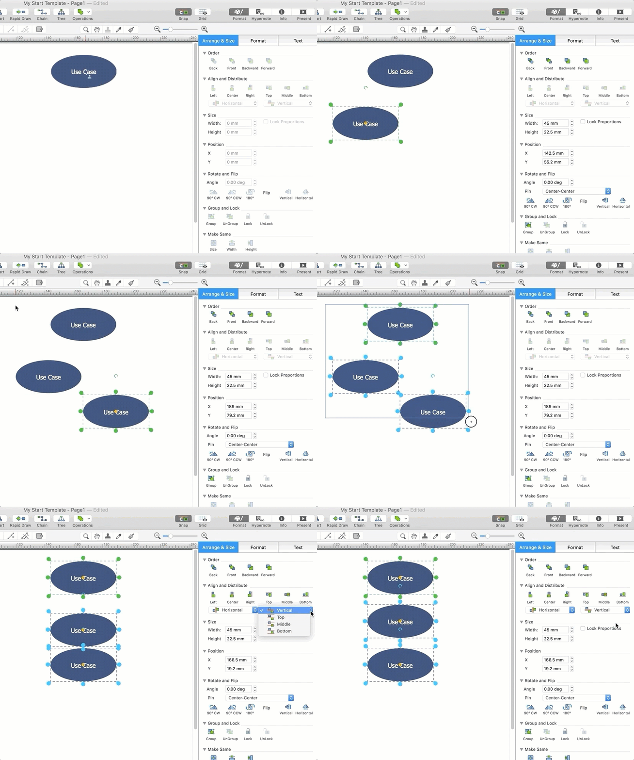
- Drag and drop elements onto the document page and arrange them as necessary using tools provided in the Arrange&Size panel.
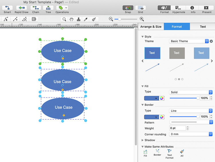
- Format objects using the set of pre-designed styles. Each format style includes the pre-designed color of an object's fill and border along with effects and text formatting.
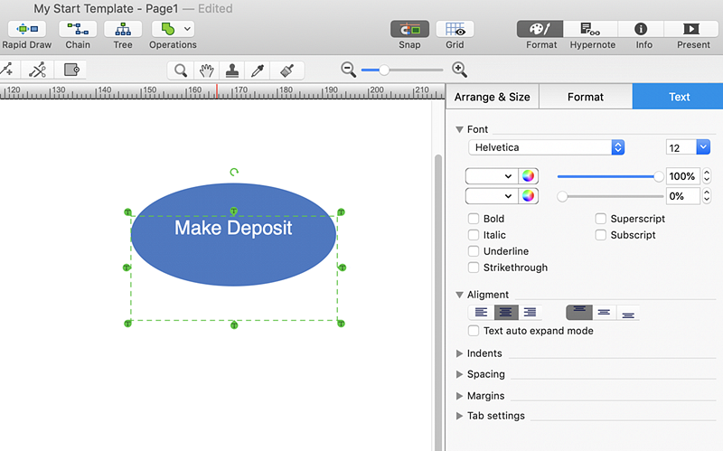
- Next add the text to the diagram. To do this, select an object and start typing.
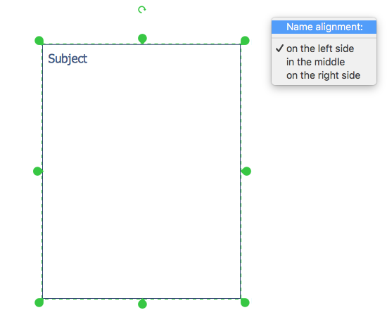
- Some of bank UML libraries contain objects, identified by a blue tile in the library pane. These objects can be edited using the Action button menu. To open the menu select, an object and click the
 action button in the upper right corner of the object. action button in the upper right corner of the object.
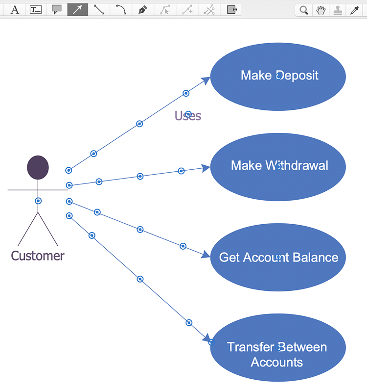
- Select the Direct Connector tool. To connect elements using this tool, drag the connector from one connect dot to another.
Result:The ATM UML Diagrams solution can be used by banking software specialists developing ATM solutions and systems of any complexity.
|
How it works:
- Set of ready-to-use templates supplied with ConceptDraw DIAGRAM
- Collection of professional samples supports each template
Useful Solutions and Products:
- Bank UML Activity Diagram
- Bank UML Class Diagram
- Bank UML Communication Diagram
- Bank UML Component Diagram
- Bank UML Composite Structure Diagram
- Bank UML Deployment Diagram
- Bank UML Interaction Overview Diagram
- Bank UML Profile Diagram
- Bank UML Package Diagram
- Bank UML Sequence Diagram
- Bank UML State Machine Diagram
- Bank UML Timing Diagram
- Bank UML Use Case Diagram
- Bank UML Object Diagram
- Diagraming and Charts
- Vector Illustrations
- Maps
- Floor plans
- Engineering drawings
- Business dashboards
- Infographics
- Presentation
- Over 10 000 vector stencils
- Export to vector graphics files
- Export to Adobe Acrobat® PDF
- Export to MS PowerPoint®
- Export to MS Visio® VSDX, VDX
|


 Business-specific Drawings