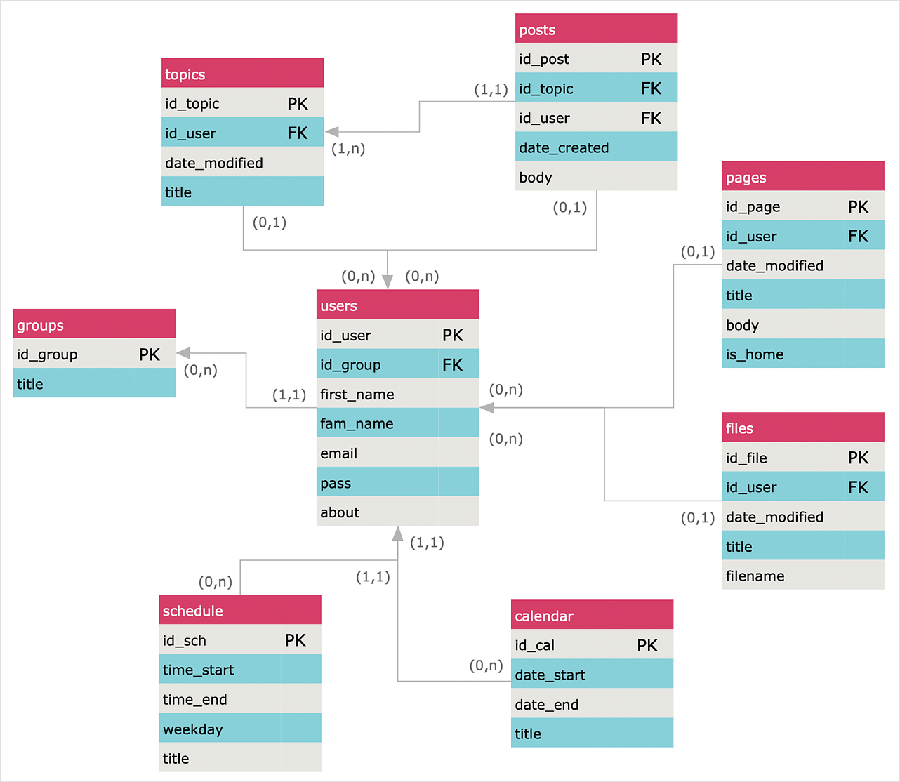
How to Create an Entity-Relationship DiagramEntity-relationship diagrams (ERD) follow the common three-schema approach to software engineering, with three levels of abstraction being used to define an ER model. A conceptual data model is the most abstract view of a data model. It offers a complete overview of a business area, including all significant business entities, and describing their relationships. It omits further levels of detail, including data types and interface definitions, making it suitable as a means of presenting an initial business idea to a wide range of stakeholders. Using Logical data model a higher level of detail is established, with data entities describe as master, operational or transactional, and the relationships between them more precisely defined. This is the testing phase of a data model, where functionality can be observed independently of physical specifications. When building a Physical data model, data modelers start to take into account the physical constraints of the database area. Important factors to consider are database performance, physical storage space, and indexing strategy. Diagram notations will fully define all tables and columns, indexes, constraint definitions, and any linking or partitioned tables. The ability to describe a database using the Entity-Relationship model is delivered by the Entity-Relationship Diagram (ERD) solution. This solution extends ConceptDraw DIAGRAM with 2 libraries that contain 45 objects advocated by Chen's and Crow’s Foot notations that can be used when describing a database.


Result: Entity-relationship diagram (ERD) represents a conceptual schema or semantic data model of a software system. |
How it works:
Useful Solutions and Products:
|
 Business-specific Drawings
  . To connect elements using this tool, drag the connector from one connect dot to another.