ConceptDraw products continue to be an attractive solution because of their state-of-the-art approach to productivity, project planning, and knowledge organization. In its second iteration, the ConceptDraw Office Suite (comprised of ConceptDraw MINDMAP, ConceptDraw PROJECT, and ConceptDraw DIAGRAM ) has improved every facet of the product’s performance, from enhanced stability to a tighter integration between the three software components. New to ConceptDraw Office v2 is the ConceptDraw Solution Park, which gives users access to a growing online collection of business-specific plug-ins.
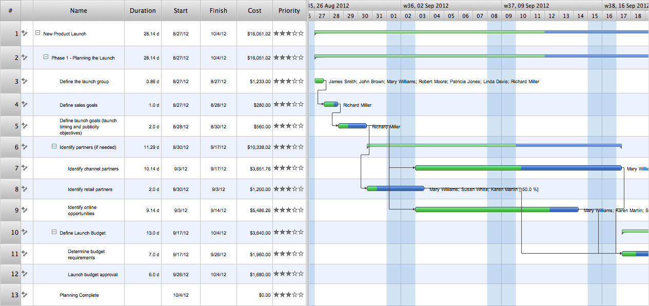
In this tutorial video we will assist you in planning and managing a project using ConceptDraw Office.
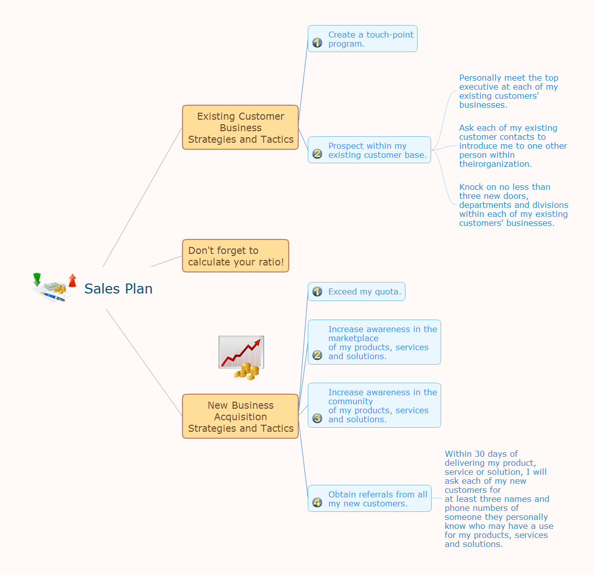
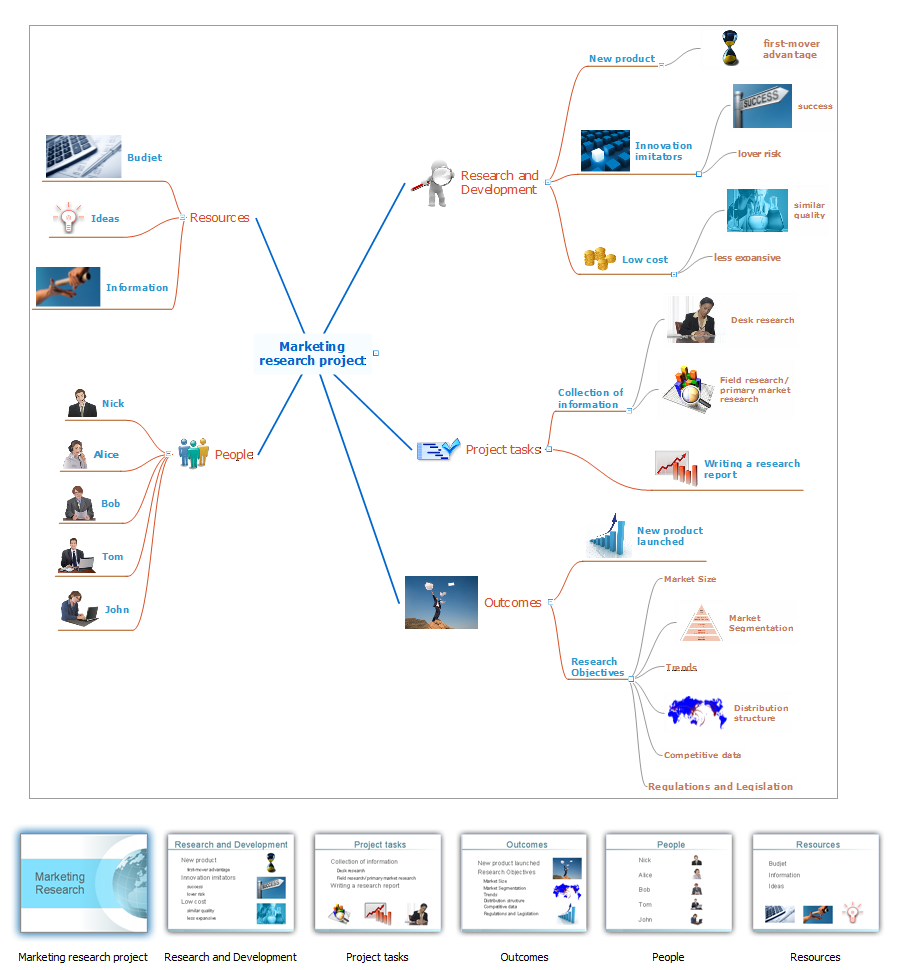
The easiest way to start a new project is to conduct a brainstorm session that identifies the necessary tasks. You can then prepare a project schedule and assign resources to these tasks.
This video shows you how ConceptDraw Office can save you hours of work when starting a new project.
ConceptDraw Office is the most effective tool for planning, tracking, and reporting all types of projects with strong management capabilities, user friendly functionality, and superior ease of use.
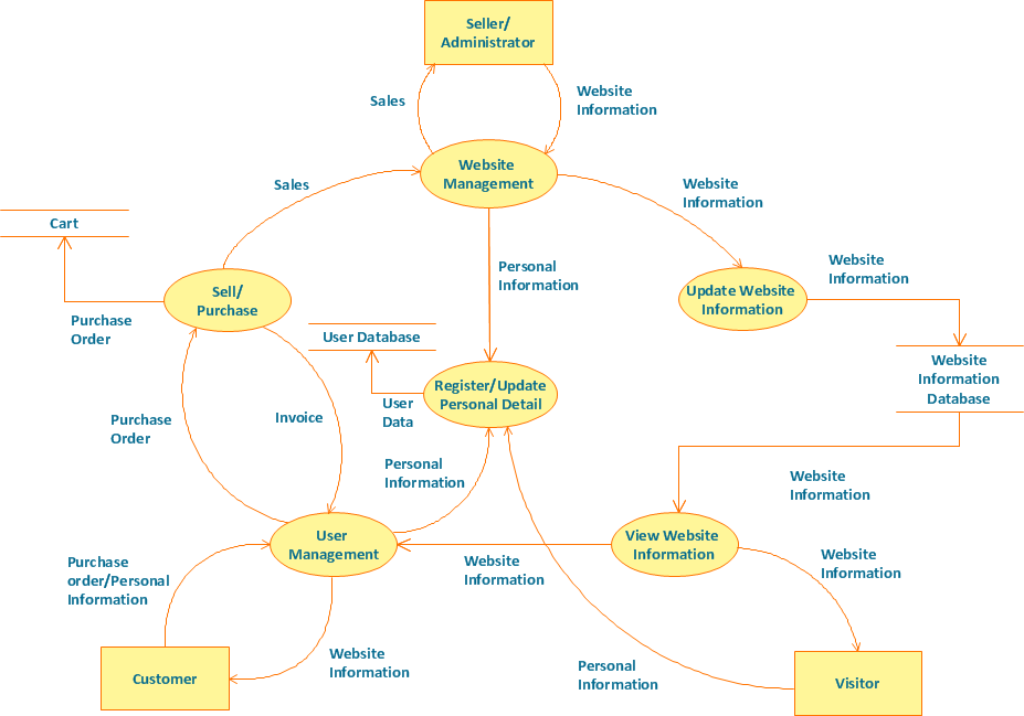
Structured-systems analysis and design method uses data flow diagrams to represent the process of data flowing through a system. Talking about this might be useless without a proper example of DFD for online store (Data Flow Diagram). This DFD example shows all the distinctness that a diagram can bring into a scattered data structure.
Data flow diagrams are used to show how data is processed within some business processes. Making DFD is a common practice for business process modeling and analysis. This diagram represents the online store business flow. It describes inputs and outputs within online selling process and depicts the interactions between its participants. This DF diagram can be used by system analysts to create an overview of a business, to study and discover its inherent strengths and weak points.
Picture: Example of DFD for Online Store (Data Flow Diagram)
Still doubting about the number of tables in your cafe? You should create a cafe floor plan that will answer all your questions and reflect all the details of your cafe interior. Get started in several minutes and unlock your creativity with dozens of ConceptDraw DIAGRAM templates and examples!
Dealing with interiors plans for HoReCa business, for example, developing a plan for cafe you will meet with both creative and architectural challenges. First of all , the layout of cafe should be beautiful and convenient for visitors. Being developed sagely a plan of your cafe leads to successful sales and good benefits. Designing a cafe floor plan includes various elements that can be picked out using ConceptDraw Cafe and Restaurant Floor Plan solution. The vector objects library supplied with Cafe and Restaurant solution provides a number of graphic objects for displaying different layouts and styles of catering establishments.
Picture: Cafe Floor Plan. Cafe Floor Plan Examples
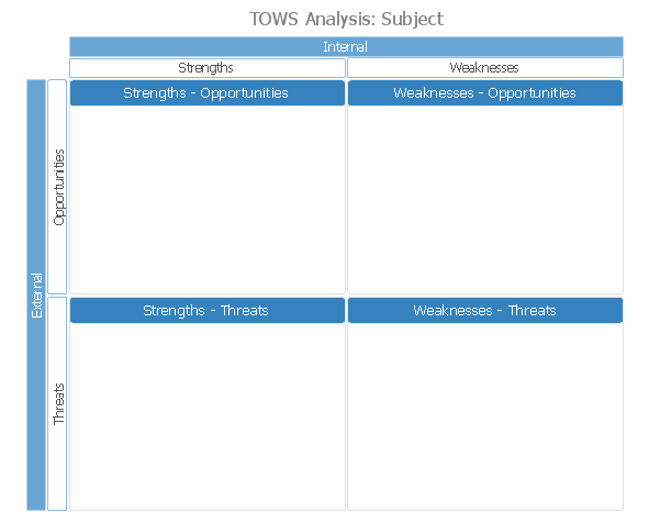
TOWS analysis is a method of strategic analysis which is oriented on the study of the threats (T) which are danger for the company and new opportunities (O) which are closely connected with weaknesses (W) and strengths (S) sides of its activity.
ConceptDraw DIAGRAM diagramming and vector drawing software extended with SWOT and TOWS Matrix Diagrams Solution from the Management Area is the best for realization TOWS analysis and for quick and easy construction TOWS Matrix.
ConceptDraw DIAGRAM extended with Chemistry solution is effective for drawing various organic chemistry schemes, diagrams, illustrations thanks to the included collection of predesigned organic chemistry symbols
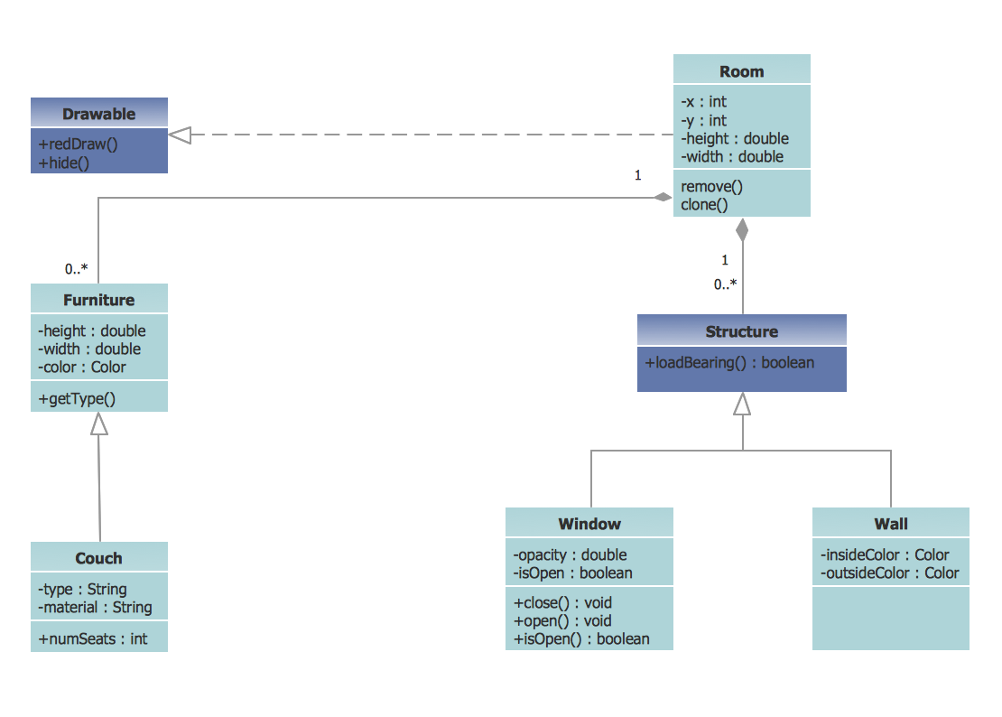
UML Apartment Plan. This sample was created in ConceptDraw DIAGRAM diagramming and vector drawing software using the UML Class Diagram library of the Rapid UML Solution from the Software Development area of ConceptDraw Solution Park.
This sample show the detailed plan of the apartment and is used by building companies, design apartments, real estate agencies, at the buying / selling of the realty.
Picture: UML Class Diagram Example - Apartment Plan