"Driving is the controlled operation and movement of a vehicle, such as a car, carriage, truck or bus. ...
Driving as a physical skill.
A driver must have physical skills to be able to control direction, acceleration, and deceleration. For motor vehicles, the detailed tasks include:
(1) Starting the vehicle's engine with the starting system.
(2) Setting the transmission to the correct gear.
(3) Depressing the pedals with one's feet to accelerate, slow, and stop the vehicle, and if the vehicle is equipped with a manual transmission, to modulate the clutch.
(4) Steering the vehicle's direction with the steering wheel.
(5) Operating other important ancillary devices such as the indicators, headlights, and windshield wipers.
(6) Observing the environment for hazards." [Driving. Wikipedia]
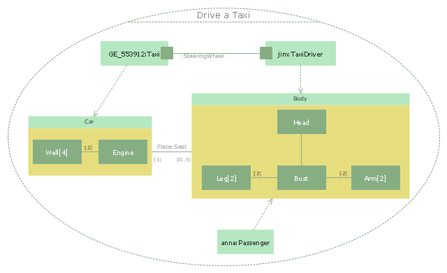
The UML composite structure diagram example "Drive a taxi" was created using the ConceptDraw PRO diagramming and vector drawing software extended with the Rapid UML solution from the Software Development area of ConceptDraw Solution Park.
"Business process improvement (BPI) is a systematic approach to help an organization optimize its underlying processes to achieve more efficient results. ...
An organization is only as good as its processes. To be able to make the necessary changes in an organization, one needs to understand the key processes of the company. Rummler and Brache suggested a model for running a Process Improvement and Management project (PI&M), containing the following steps:
1. Identify the process to be improved (based on a critical business issue): The identification of key processes can be a formal or informal exercise. The management team might select processes by applying a set of criteria derived from strategic and tactical priorities, or process selection is based on obvious performance gaps. It is important is to select the process(es) which have the greatest impact on a competitive advantage or customer requirement.
2. Develop the objective(s) for the project based on the requirements of the process: The focus might be on quality improvement, productivity, cost, customer service or cycle time. The goal is however always the same; to get the key process under control.
3. Select the members of the cross-functional team: A horizontal (cross-functional) analysis is carried out by a team composed of representatives of all functions involved in the process. While a consultant or in-house staff person can do the job, the quality of the analysis and the commitment to change is far greater with a cross-functional team.
4. Document the current process by creating a flowchart or "organization map": Describe the process regarding the Organizational level, the Process level and the Job/ Performer level according to Rummler. Develop a cross-functional process map for the process.
5. Identify "disconnects" in the process: “Disconnections” are everything that inhibit the efficiency and effectiveness of the process. The identification should be categorized into the three levels: The Organizational level, the Process level and the Job/ Performer level.
6. Recommend changes (organizational, in the process or in its execution): Categorize and prioritize the main problems and possibilities, evaluate alternative solutions. Develop a cross-functional process map for the recommended process.
7. Establish process and sub-process measures: The process measures should reflect the objectives of the project.
8. Implement the improvements." [Business process improvement. Wikipedia]
The opportunity flow chart example "Replacing engine oil" was created using the ConceptDraw PRO diagramming and vector drawing software extended with the Cross-Functional Flowcharts solution from the Business Processes area of ConceptDraw Solution Park.
The vector stencils library "Cisco network topology" contains 89 symbols of Cisco network devices and design elements for drawing computer network topology diagrams.
"There are two basic categories of network topologies:
(1) Physical topologies,
(2) Logical topologies.
The shape of the cabling layout used to link devices is called the physical topology of the network. This refers to the layout of cabling, the locations of nodes, and the interconnections between the nodes and the cabling. The physical topology of a network is determined by the capabilities of the network access devices and media, the level of control or fault tolerance desired, and the cost associated with cabling or telecommunications circuits.
The logical topology in contrast, is the way that the signals act on the network media, or the way that the data passes through the network from one device to the next without regard to the physical interconnection of the devices." [Network topology. Wikipedia]
The symbols example "Cisco network topology - Vector stencils library" was created using the ConceptDraw PRO diagramming and vector drawing software extended with the Cisco Network Diagrams solution from the Computer and Networks area of ConceptDraw Solution Park.
www.conceptdraw.com/ solution-park/ computer-networks-cisco
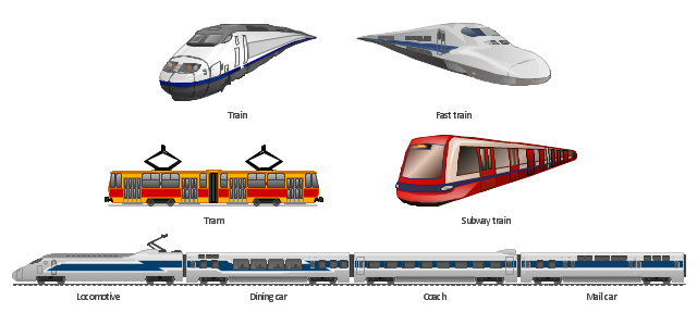
The vector clipart library Rail transport contains 8 images: railway train, fast train, subway train, tram, locomotive, dining car, coach, mail car.
Use the vector stencils library Rail transport to draw train illustrations, presentation slides, infographics and diagrams using the ConceptDraw PRO diagramming and vector drawing software.
"Rail transport is a means of conveyance of passengers and goods, by way of wheeled vehicles running on rails. It is also commonly referred to as train transport. In contrast to road transport, where vehicles merely run on a prepared surface, rail vehicles are also directionally guided by the tracks on which they run. Track usually consists of steel rails installed on sleepers/ ties and ballast, on which the rolling stock, usually fitted with metal wheels, moves. However, other iations are also possible, such as slab track where the rails are fastened to a concrete foundation resting on a prepared subsurface. Rolling stock in railway transport systems generally has lower frictional resistance when compared with highway vehicles and the passenger and freight cars (carriages and wagons) can be coupled into longer trains. The operation is carried out by a railway company, providing transport between train stations or freight customer facilities. Power is provided by locomotives which either draw electrical power from a railway electrification system or produce their own power, usually by diesel engines. Most tracks are accompanied by a signalling system. Railways are a safe land transport system when compared to other forms of transport." [Rail transport. Wikipedia]
The design elements library Rail transport is included in the Aerospace and Transport solution from the Illustration area of ConceptDraw Solution Park.
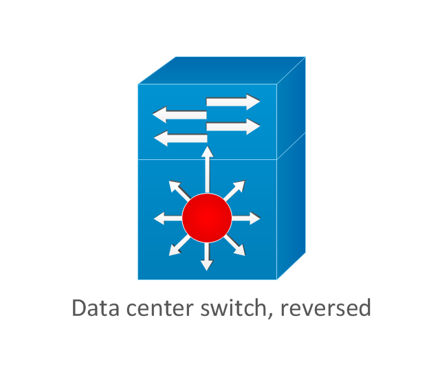
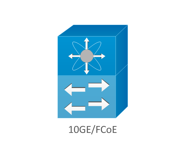
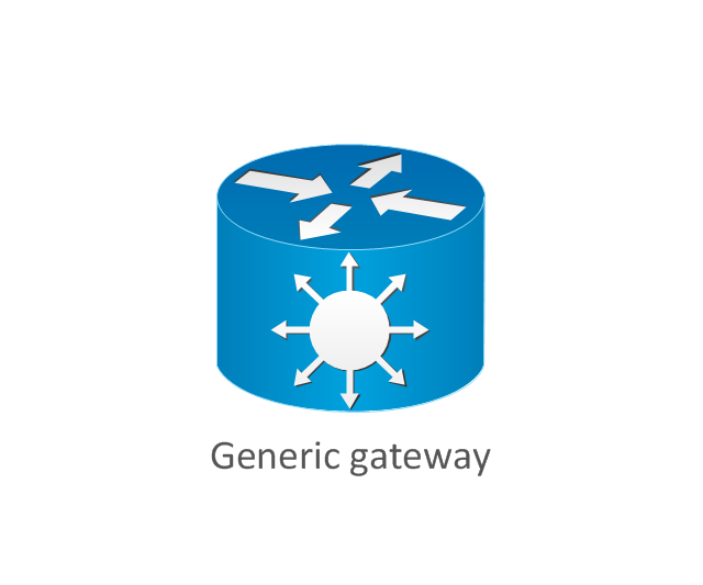
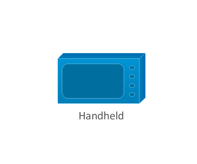
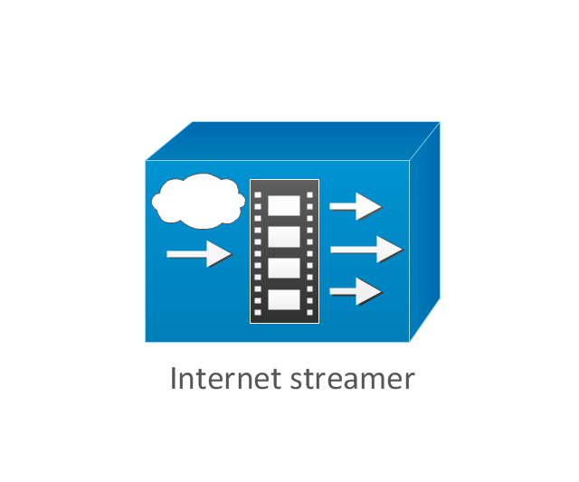
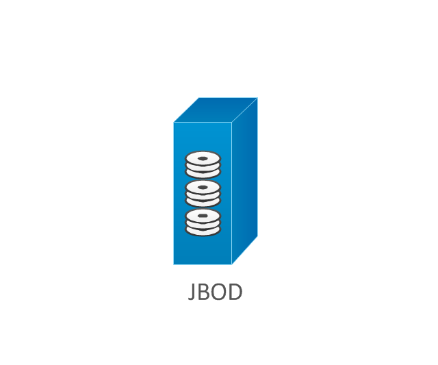
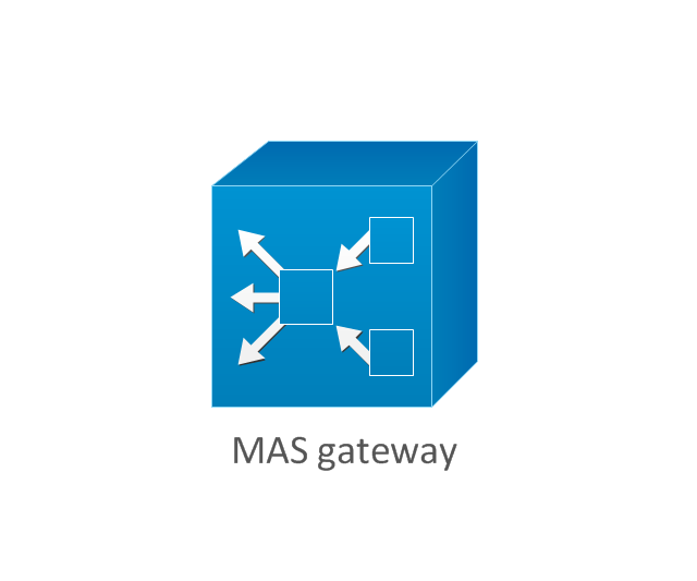
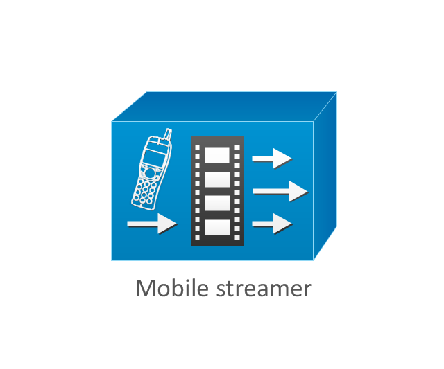
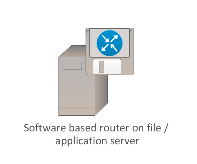
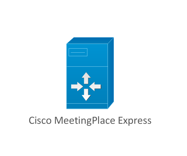
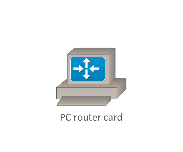
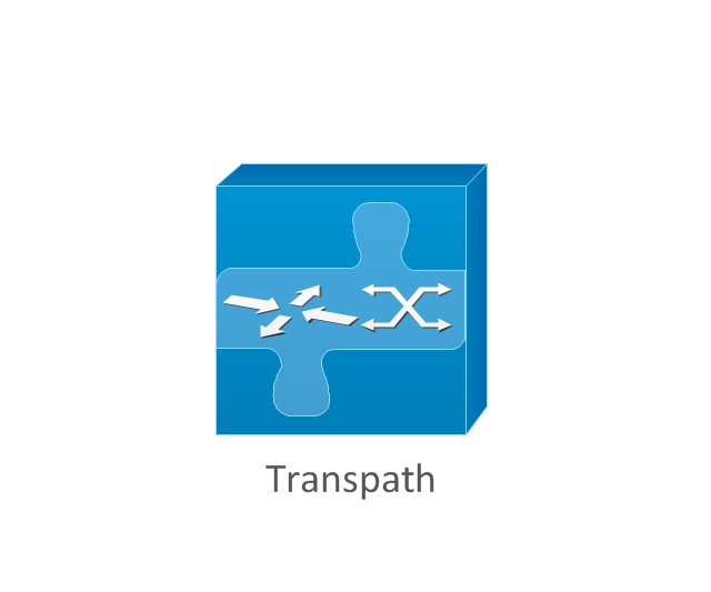
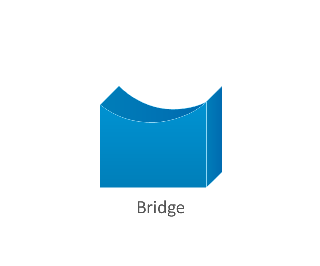
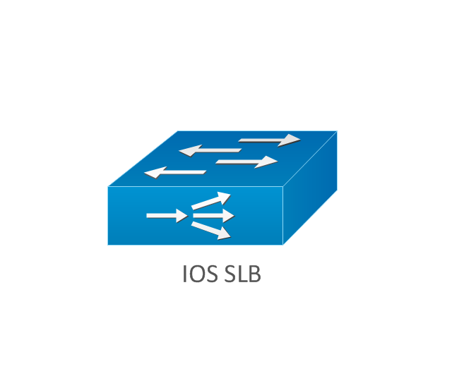
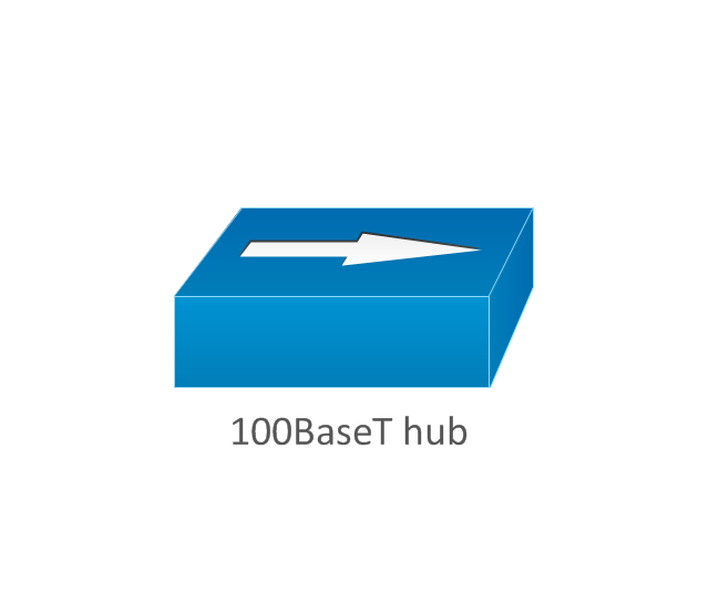
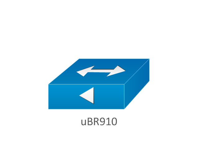
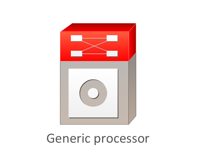
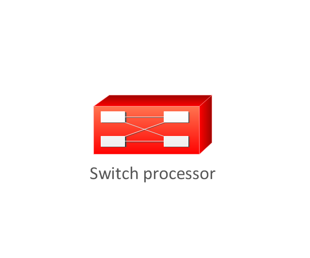
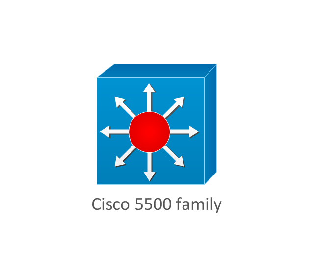
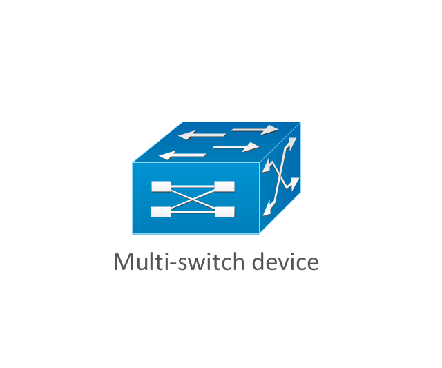
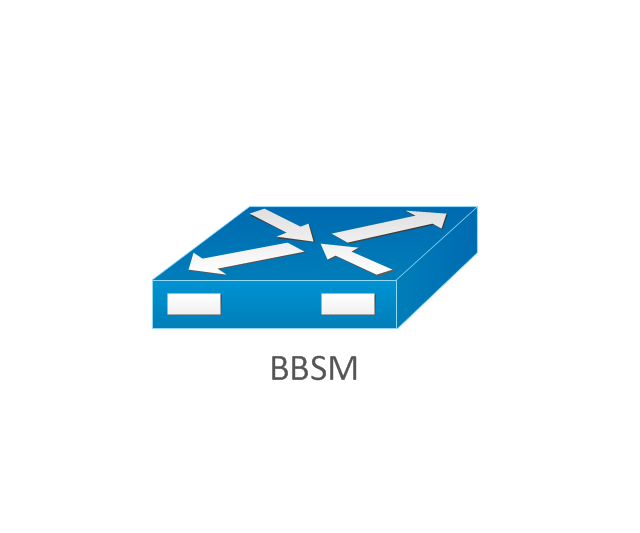
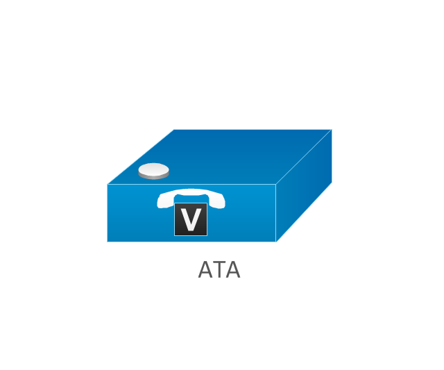
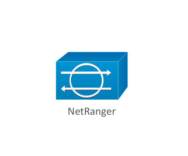
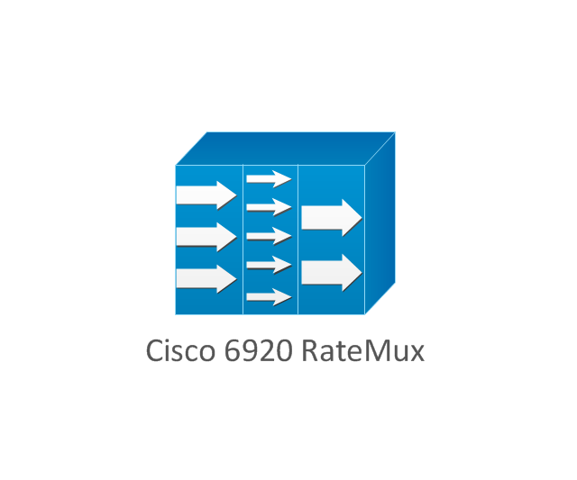
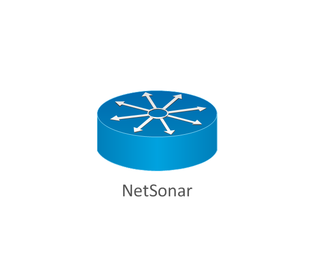
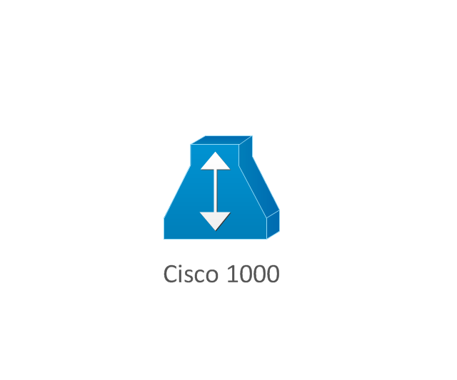
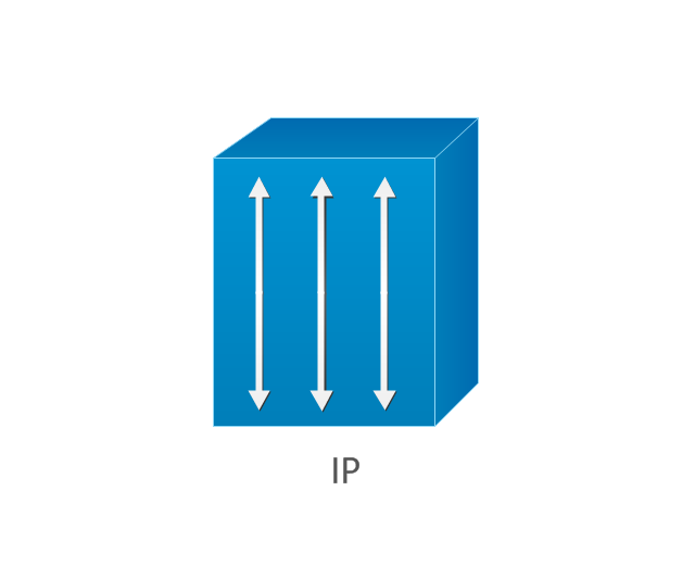
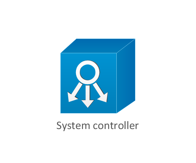
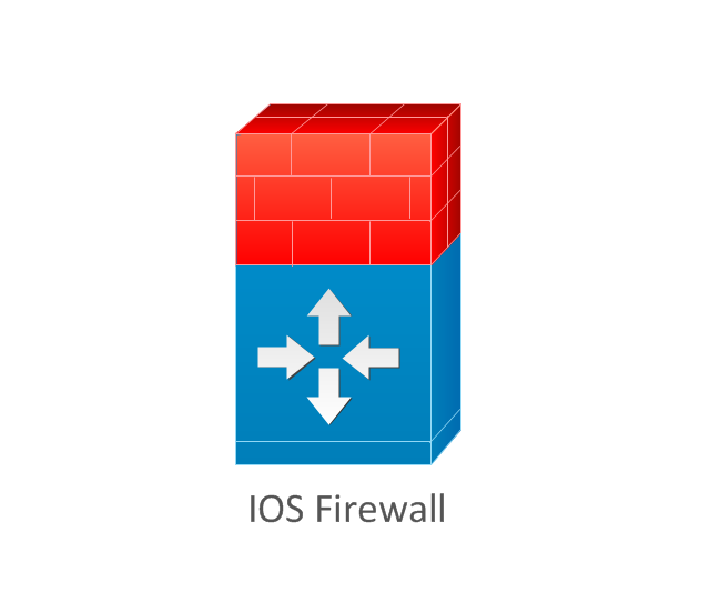
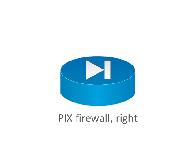
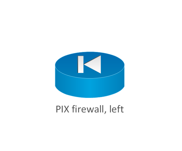
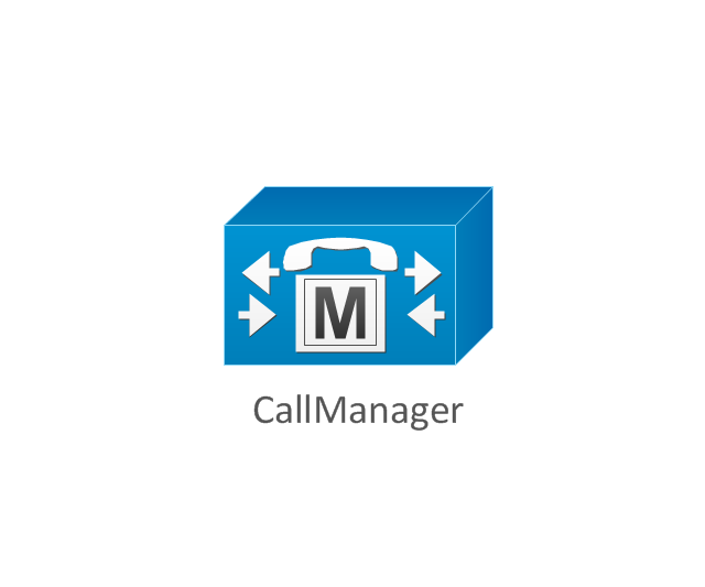
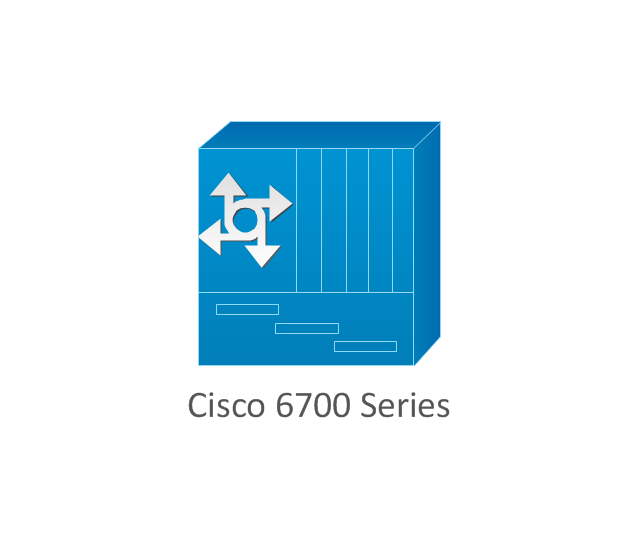
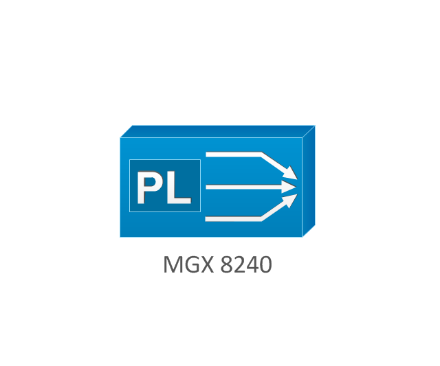
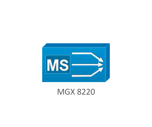
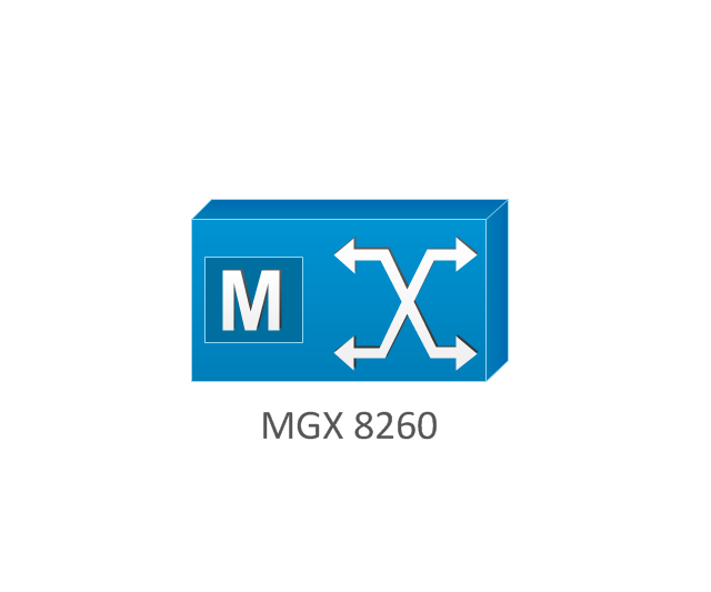
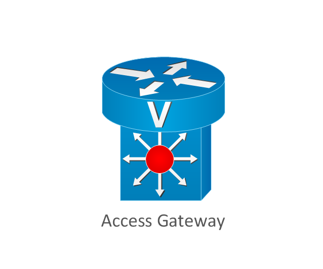
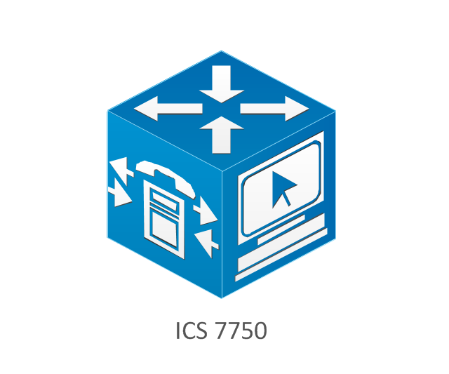
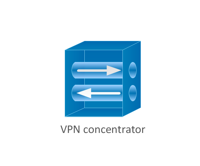
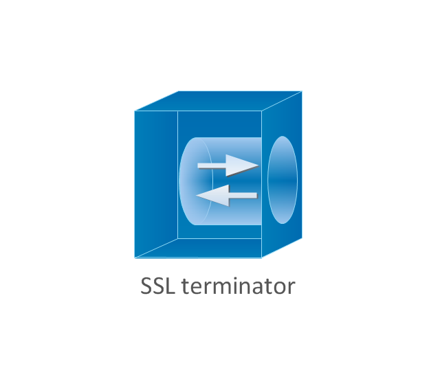
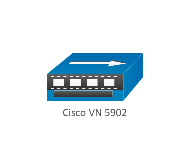
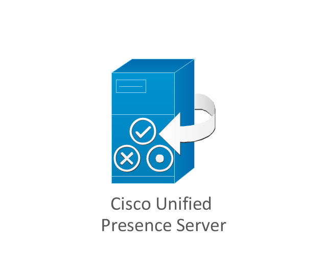
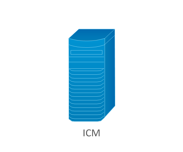
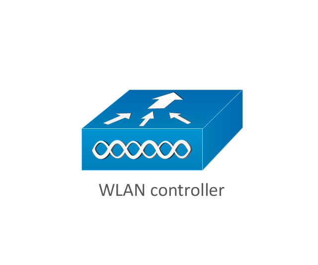
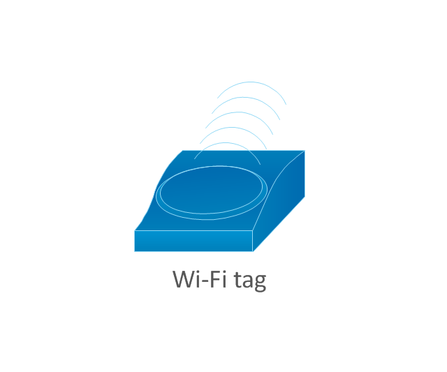
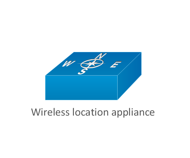
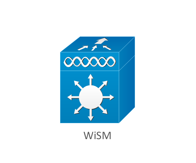
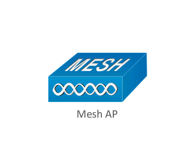
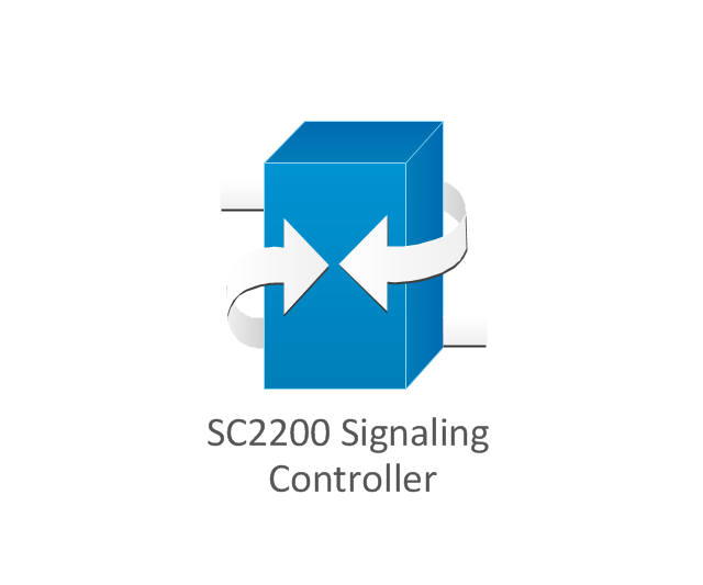
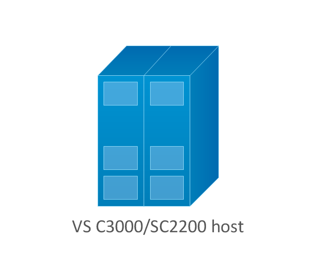
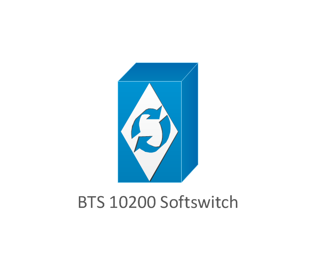
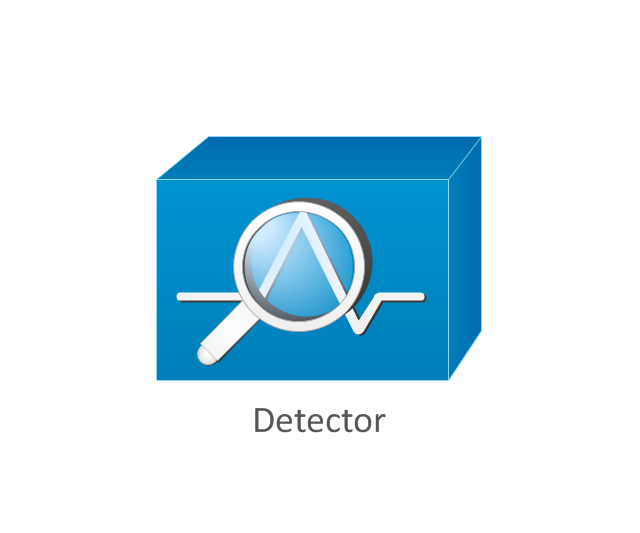
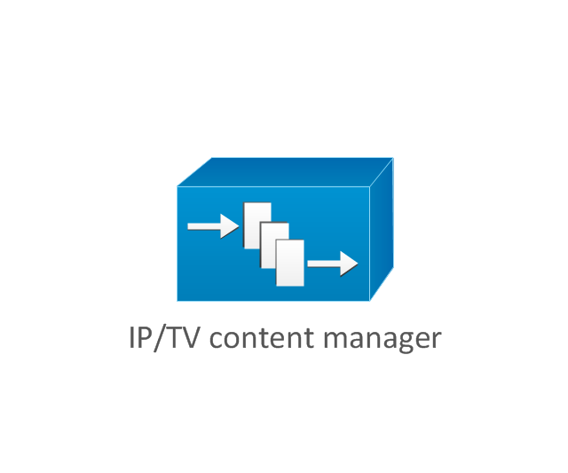
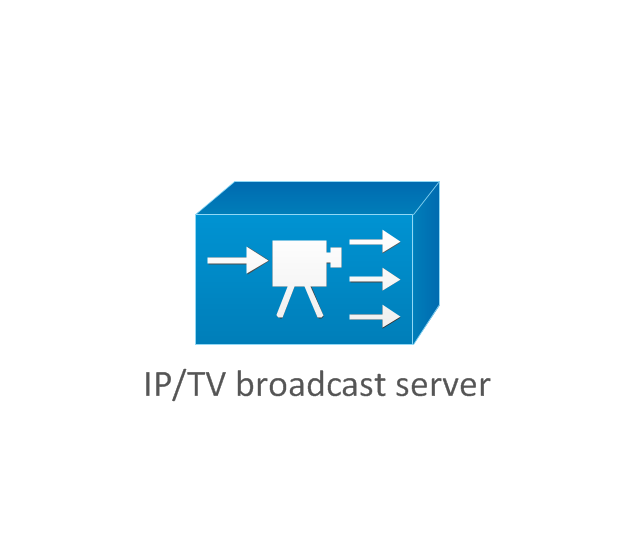
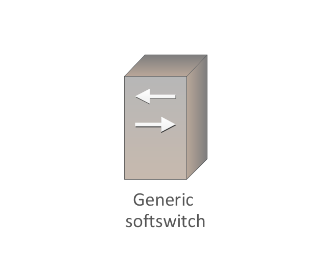
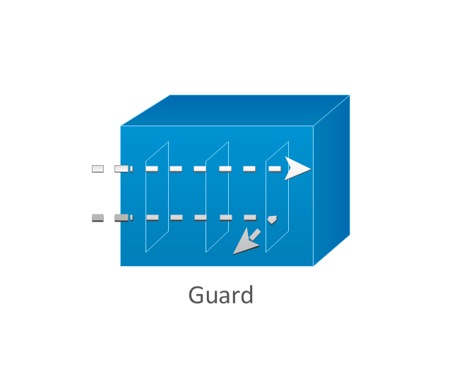
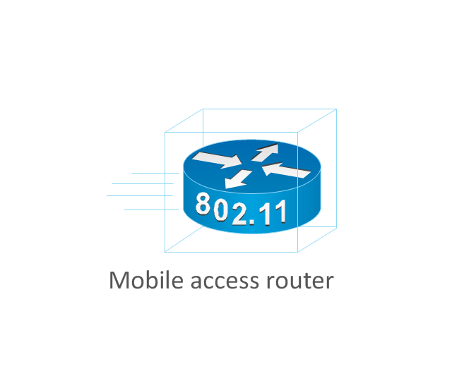
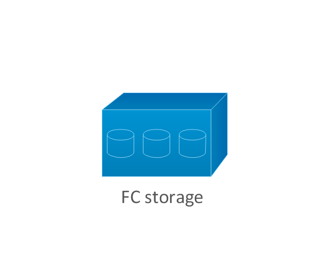
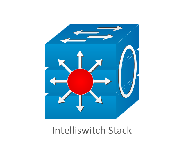
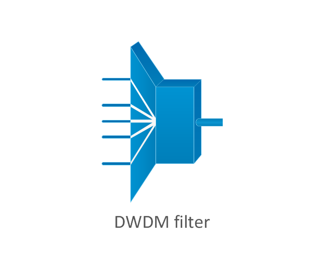
The vector stencils library "Cisco products additional" contains 141 symbols of computer network devices and equipment for drawing Cisco network diagrams.
The symbols example "Cisco products additional - Vector stencils library" was created using the ConceptDraw PRO diagramming and vector drawing software extended with the Cisco Network Diagrams solution from the Computer and Networks area of ConceptDraw Solution Park.
www.conceptdraw.com/ solution-park/ computer-networks-cisco
The vector stencils library "Pumps" contains 82 symbols of pumps, compressors, fans, turbines, and power generators.
Use these icons to design pumping systems, air and fluid compression systems, and industrial process diagrams.
"A pump is a device that moves fluids (liquids or gases), or sometimes slurries, by mechanical action. Pumps can be classified into three major groups according to the method they use to move the fluid: direct lift, displacement, and gravity pumps.
Pumps operate by some mechanism (typically reciprocating or rotary), and consume energy to perform mechanical work by moving the fluid. Pumps operate via many energy sources, including manual operation, electricity, engines, or wind power, come in many sizes, from microscopic for use in medical applications to large industrial pumps.
Mechanical pumps serve in a wide range of applications such as pumping water from wells, aquarium filtering, pond filtering and aeration, in the car industry for water-cooling and fuel injection, in the energy industry for pumping oil and natural gas or for operating cooling towers. In the medical industry, pumps are used for biochemical processes in developing and manufacturing medicine, and as artificial replacements for body parts, in particular the artificial heart and penile prosthesis.
In biology, many different types of chemical and bio-mechanical pumps have evolved, and biomimicry is sometimes used in developing new types of mechanical pumps." [Pump. Wikipedia]
The example "Design elements - Pumps" was created using the ConceptDraw PRO diagramming and vector drawing software extended with the Chemical and Process Engineering solution from the Engineering area of ConceptDraw Solution Park.
The vector stencils library "Cisco products additional" contains 141 symbols of computer network devices and equipment for drawing Cisco network diagrams.
The symbols example "Cisco products additional - Vector stencils library" was created using the ConceptDraw PRO diagramming and vector drawing software extended with the Cisco Network Diagrams solution from the Computer and Networks area of ConceptDraw Solution Park.
www.conceptdraw.com/ solution-park/ computer-networks-cisco
The symbols example "Cisco products additional - Vector stencils library" was created using the ConceptDraw PRO diagramming and vector drawing software extended with the Cisco Network Diagrams solution from the Computer and Networks area of ConceptDraw Solution Park.
www.conceptdraw.com/ solution-park/ computer-networks-cisco
The vector stencils library "Cisco network topology" contains 89 symbols of Cisco network devices and design elements for drawing computer network topology diagrams.
"There are two basic categories of network topologies:
(1) Physical topologies,
(2) Logical topologies.
The shape of the cabling layout used to link devices is called the physical topology of the network. This refers to the layout of cabling, the locations of nodes, and the interconnections between the nodes and the cabling. The physical topology of a network is determined by the capabilities of the network access devices and media, the level of control or fault tolerance desired, and the cost associated with cabling or telecommunications circuits.
The logical topology in contrast, is the way that the signals act on the network media, or the way that the data passes through the network from one device to the next without regard to the physical interconnection of the devices." [Network topology. Wikipedia]
The symbols example "Cisco network topology - Vector stencils library" was created using the ConceptDraw PRO diagramming and vector drawing software extended with the Cisco Network Diagrams solution from the Computer and Networks area of ConceptDraw Solution Park.
www.conceptdraw.com/ solution-park/ computer-networks-cisco
"There are two basic categories of network topologies:
(1) Physical topologies,
(2) Logical topologies.
The shape of the cabling layout used to link devices is called the physical topology of the network. This refers to the layout of cabling, the locations of nodes, and the interconnections between the nodes and the cabling. The physical topology of a network is determined by the capabilities of the network access devices and media, the level of control or fault tolerance desired, and the cost associated with cabling or telecommunications circuits.
The logical topology in contrast, is the way that the signals act on the network media, or the way that the data passes through the network from one device to the next without regard to the physical interconnection of the devices." [Network topology. Wikipedia]
The symbols example "Cisco network topology - Vector stencils library" was created using the ConceptDraw PRO diagramming and vector drawing software extended with the Cisco Network Diagrams solution from the Computer and Networks area of ConceptDraw Solution Park.
www.conceptdraw.com/ solution-park/ computer-networks-cisco
- Car Engine Block Diagram With Air Conditioning System
- Engine Block Diagram
- Car Engine Basic Diagram And Block Diagram
- Block Diagrams
- Block diagram - Automotive HVAC system | HVAC Plans | Functional ...
- A Sketch Of An Engine Block Diagram
- Block diagram - Automotive HVAC system | Automobile Air ...
- Car Air Conditioning System Block Diagram
- Block diagram - Automotive HVAC system | Block Diagram Of Car Ac ...
- Block diagram - Automotive HVAC system | Effect Of Hvac In Vehicle ...
- Block diagram - Automotive HVAC system | Functional Block ...
- Block diagram - Automotive HVAC system | HVAC Plans | Block ...
- Block diagram - Automotive HVAC system | Block diagram ...
- Block diagram - Automotive HVAC system | Block Diagram Of Car ...
- Block diagram - Gap model of service quality | Block diagram ...
- Functional Block Diagram Of An Automobile System
- Block Diagram Of Engine
- Block diagram - Automotive HVAC system | Create Block Diagram ...
- Block diagram - Automotive HVAC system | HVAC Plans | Cable TV ...
- Block diagram - Automotive HVAC system | HVAC Plans | Create ...


-cisco-network-topology---vector-stencils-library.png--diagram-flowchart-example.png)
-cisco-network-topology---vector-stencils-library.png--diagram-flowchart-example.png)


-cisco-network-topology---vector-stencils-library.png--diagram-flowchart-example.png)


-cisco-network-topology---vector-stencils-library.png--diagram-flowchart-example.png)


-cisco-network-topology---vector-stencils-library.png--diagram-flowchart-example.png)



-cisco-products-additional---vector-stencils-library.png--diagram-flowchart-example.png)
-cisco-products-additional---vector-stencils-library.png--diagram-flowchart-example.png)
-cisco-products-additional---vector-stencils-library.png--diagram-flowchart-example.png)
-cisco-products-additional---vector-stencils-library.png--diagram-flowchart-example.png)


-cisco-products-additional---vector-stencils-library.png--diagram-flowchart-example.png)
-cisco-products-additional---vector-stencils-library.png--diagram-flowchart-example.png)

-cisco-products-additional---vector-stencils-library.png--diagram-flowchart-example.png)
-cisco-products-additional---vector-stencils-library.png--diagram-flowchart-example.png)

-cisco-products-additional---vector-stencils-library.png--diagram-flowchart-example.png)

-cisco-products-additional---vector-stencils-library.png--diagram-flowchart-example.png)

-cisco-products-additional---vector-stencils-library.png--diagram-flowchart-example.png)
-cisco-products-additional---vector-stencils-library.png--diagram-flowchart-example.png)
-cisco-products-additional---vector-stencils-library.png--diagram-flowchart-example.png)

-cisco-products-additional---vector-stencils-library.png--diagram-flowchart-example.png)
-cisco-products-additional---vector-stencils-library.png--diagram-flowchart-example.png)
