- Electric and Telecom Plans Free
- Fire and Emergency Plans Free
- Floor Plans Free
- Plant Layout Plans Free
- School and Training Plans Free
- Seating Plans Free
- Security and Access Plans Free
- Site Plans Free
- Sport Field Plans Free
- Business Process Diagrams Free
- Business Process Mapping Free
- Classic Business Process Modeling Free
- Cross-Functional Flowcharts Free
- Event-driven Process Chain Diagrams Free
- IDEF Business Process Diagrams Free
- Logistics Flow Charts Free
- Workflow Diagrams Free
- ConceptDraw Dashboard for Facebook Free
- Mind Map Exchange Free
- MindTweet Free
- Note Exchange Free
- Project Exchange Free
- Social Media Response Free
- Active Directory Diagrams Free
- AWS Architecture Diagrams Free
- Azure Architecture Free
- Cisco Network Diagrams Free
- Cisco Networking Free
- Cloud Computing Diagrams Free
- Computer Network Diagrams Free
- Google Cloud Platform Free
- Interactive Voice Response Diagrams Free
- Network Layout Floor Plans Free
- Network Security Diagrams Free
- Rack Diagrams Free
- Telecommunication Network Diagrams Free
- Vehicular Networking Free
- Wireless Networks Free
- Comparison Dashboard Free
- Composition Dashboard Free
- Correlation Dashboard Free
- Frequency Distribution Dashboard Free
- Meter Dashboard Free
- Spatial Dashboard Free
- Status Dashboard Free
- Time Series Dashboard Free
- Basic Circle-Spoke Diagrams Free
- Basic Circular Arrows Diagrams Free
- Basic Venn Diagrams Free
- Block Diagrams Free
- Concept Maps Free
- Family Tree Free
- Flowcharts Free
- Basic Area Charts Free
- Basic Bar Graphs Free
- Basic Divided Bar Diagrams Free
- Basic Histograms Free
- Basic Line Graphs Free
- Basic Picture Graphs Free
- Basic Pie Charts Free
- Basic Scatter Diagrams Free
- Aerospace and Transport Free
- Artwork Free
- Audio, Video, Media Free
- Business and Finance Free
- Computers and Communications Free
- Holiday Free
- Manufacturing and Maintenance Free
- Nature Free
- People Free
- Presentation Clipart Free
- Safety and Security Free
- Analog Electronics Free
- Audio and Video Connectors Free
- Basic Circuit Diagrams Free
- Chemical and Process Engineering Free
- Digital Electronics Free
- Electrical Engineering Free
- Electron Tube Circuits Free
- Electronic Block Diagrams Free
- Fault Tree Analysis Diagrams Free
- GHS Hazard Pictograms Free
- Home Automation and Wiring Free
- Mechanical Engineering Free
- One-line Diagrams Free
- Power Сircuits Free
- Specification and Description Language (SDL) Free
- Telecom and AV Circuits Free
- Transport Hazard Pictograms Free
- Data-driven Infographics Free
- Pictorial Infographics Free
- Spatial Infographics Free
- Typography Infographics Free
- Calendars Free
- Decision Making Free
- Enterprise Architecture Diagrams Free
- Fishbone Diagrams Free
- Organizational Charts Free
- Plan-Do-Check-Act (PDCA) Free
- Seven Management and Planning Tools Free
- SWOT and TOWS Matrix Diagrams Free
- Timeline Diagrams Free
- Australia Map Free
- Continent Maps Free
- Directional Maps Free
- Germany Map Free
- Metro Map Free
- UK Map Free
- USA Maps Free
- Customer Journey Mapping Free
- Marketing Diagrams Free
- Matrices Free
- Pyramid Diagrams Free
- Sales Dashboard Free
- Sales Flowcharts Free
- Target and Circular Diagrams Free
- Cash Flow Reports Free
- Current Activities Reports Free
- Custom Excel Report Free
- Knowledge Reports Free
- MINDMAP Reports Free
- Overview Reports Free
- PM Agile Free
- PM Dashboards Free
- PM Docs Free
- PM Easy Free
- PM Meetings Free
- PM Planning Free
- PM Presentations Free
- PM Response Free
- Resource Usage Reports Free
- Visual Reports Free
- House of Quality Free
- Quality Mind Map Free
- Total Quality Management TQM Diagrams Free
- Value Stream Mapping Free
- Astronomy Free
- Biology Free
- Chemistry Free
- Language Learning Free
- Mathematics Free
- Physics Free
- Piano Sheet Music Free
- Android User Interface Free
- Class Hierarchy Tree Free
- Data Flow Diagrams (DFD) Free
- DOM Tree Free
- Entity-Relationship Diagram (ERD) Free
- EXPRESS-G data Modeling Diagram Free
- IDEF0 Diagrams Free
- iPhone User Interface Free
- Jackson Structured Programming (JSP) Diagrams Free
- macOS User Interface Free
- Object-Role Modeling (ORM) Diagrams Free
- Rapid UML Free
- SYSML Free
- Website Wireframe Free
- Windows 10 User Interface Free
Cross-Functional Flowcharts
Cross-functional flowcharts are a powerful and useful tool for visualizing and analyzing complex business processes, which require the involvement of multiple people, teams or even departments. These charts visually represent a sequence of the process steps, the order of operations, relationships between processes and responsible functional units, such as departments or positions. The cross-functional flowcharts visually delimit the process flows going between multiple functional departments, help to group sequentially the process flows during the documenting manufacturing processes, to see the interactions between stakeholders, to detect the waste, unnecessary delays and repetitive tasks. Such kind of Cross-Functional flowcharts as Opportunity flowchart is used to determine the added value in a process, to remove the processes that don't add value, and to optimize the flow of work in the process.
Cross-functional flowcharts are divided into swimlanes that provide an additional dimension by assigning each process step to a specified category. The swimlanes are used to represent the functional units and can be located horizontally or vertically depending on the type of process and one’s personal preferences. The process steps are depicted by blocks of different shapes (circles, ovals, rectangles, rounded rectangles, diamonds, etc.) located in the rows or columns of the functional units responsible for the corresponding steps and connected by directional lines. Each shape represents one step in the process.
The Cross-Functional Flowcharts solution extends ConceptDraw DIAGRAM software with cross functional flowchart examples, samples, and libraries of cross functional flow chart vector design elements and CH-1 symbols for easy drawing professional-looking and illustrative Cross Functional Flowchart, Cross Functional Diagram, CH-1 Diagram, Process Flowchart, Deployment Flowchart, Opportunity Flowchart, Swimlane Process Mapping Diagram, or Visio Cross Functional Flowchart for planning and further analyzing, optimizing and improvement processes. The use of included pre-made cross functional flowchart template, opportunity flowchart template, and swimlane process map template, greatly easier designing your Cross-functional flowcharts. This solution is incredibly helpful for the business specialists, project managers, marketing specialists, analysts, economists, politicians, and other stakeholders.
-
Install this solution Free -
What I need to get started -
Solution Requirements - This solution requires the following products to be installed:
ConceptDraw DIAGRAM v18 - This solution requires the following products to be installed:
-
Compatibility - Sonoma (14), Sonoma (15)
MS Windows 10, 11 - Sonoma (14), Sonoma (15)
-
Support for this Solution -
Helpdesk
The Cross-Functional Flowcharts solution contains 12 examples, 4 templates and 2 libraries containing 48 vector objects to allow you to create professional-looking documents.
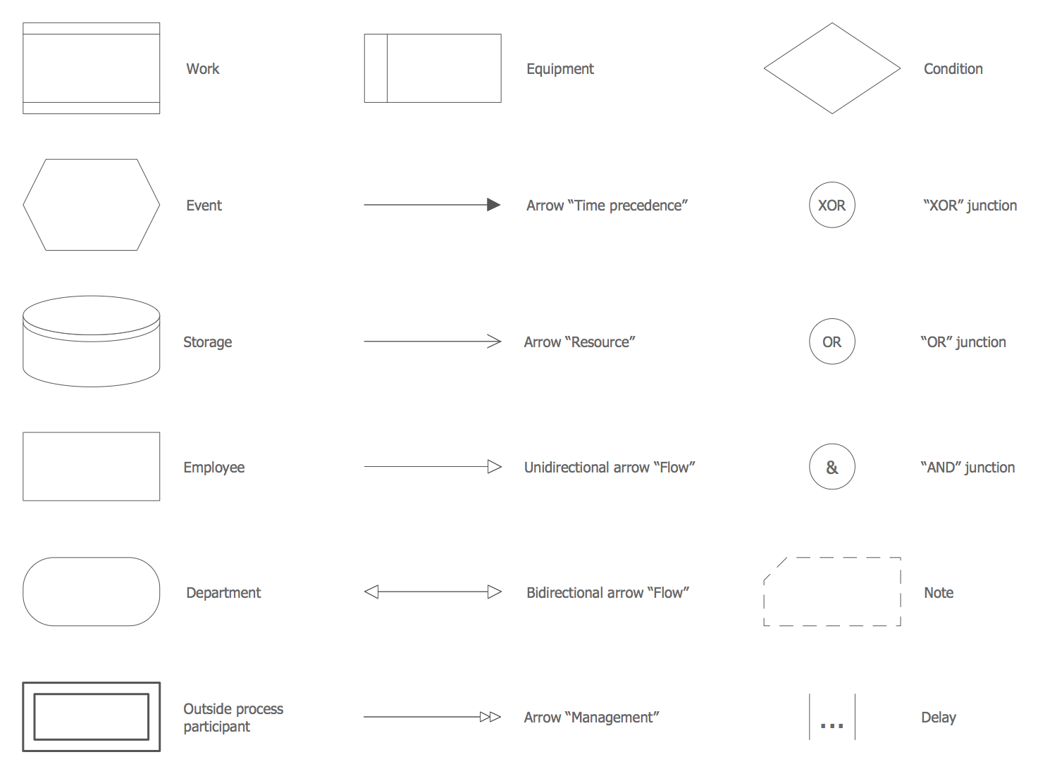
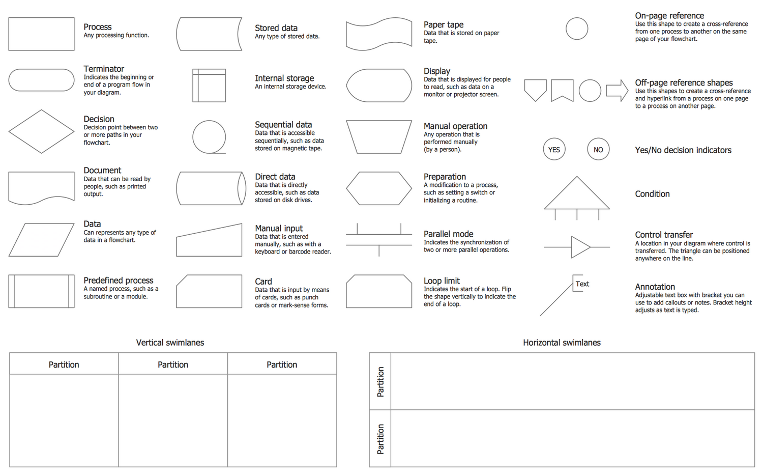
Design elements — Cross-Functional Flowcharts
Related News:
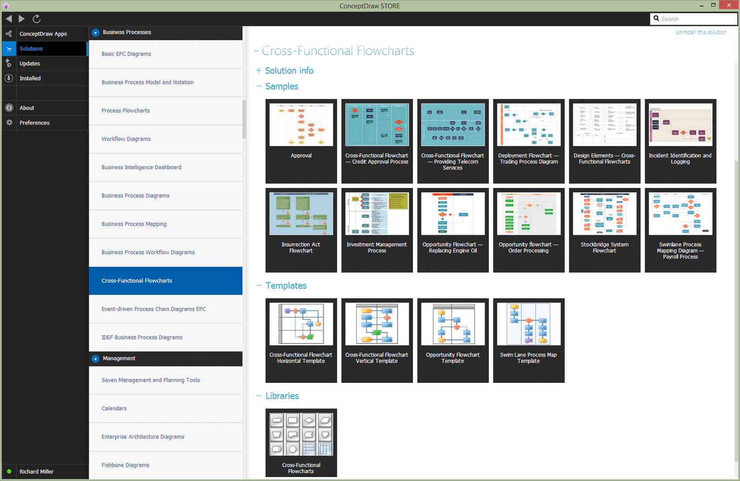
Cross-Functional Flowcharts Examples
There are a few samples that you see on this page which were created in the ConceptDraw DIAGRAM application by using the Cross-Functional Flowcharts solution. Some of the solution's capabilities as well as the professional results which you can achieve are all demonstrated here on this page.
All source documents are vector graphic documents which are always available for modifying, reviewing and/or converting to many different formats, such as MS PowerPoint, PDF file, MS Visio, and many other graphic ones from the ConceptDraw Solution Park or ConceptDraw STORE. The Cross-Functional Flowcharts solution is available to all ConceptDraw DIAGRAM users to get installed and used while working in the ConceptDraw DIAGRAM charting and drawing software.
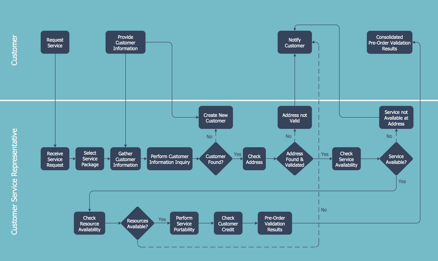
Example 1: Cross-Functional Flowchart — Providing Telecom Services
This diagram was created in ConceptDraw DIAGRAM using the Cross-Functional Flowchart library from the Cross-Functional Flowcharts Solution. An experienced user spent 15 minutes creating this sample.
This sample shows the Process Flowchart representing the process of providing the telecommunication services. The services in a telecommunication field are typically offered by the communications companies or telecommunications providers and are intended for ensuring the communication at the distance by means of modern telecommunication technologies and equipment. To be successfully realized and introduced, the process of providing the telecom services needs to be well defined and represented in a simple form. The Process Flow Chart is ideally suited for this purpose; it allows you to specify the repeating steps necessary for the implementation of this process and present them visually. In addition, it can be analyzed to improve the efficiency of the process and to diagnose the quality issues that require resolution. There are defined two horizontal lanes in this Process Flowchart: Customer and Customer Service Representative, the process steps are visually distributed within them. The diagram is read from the top down in the direction indicated by arrows.
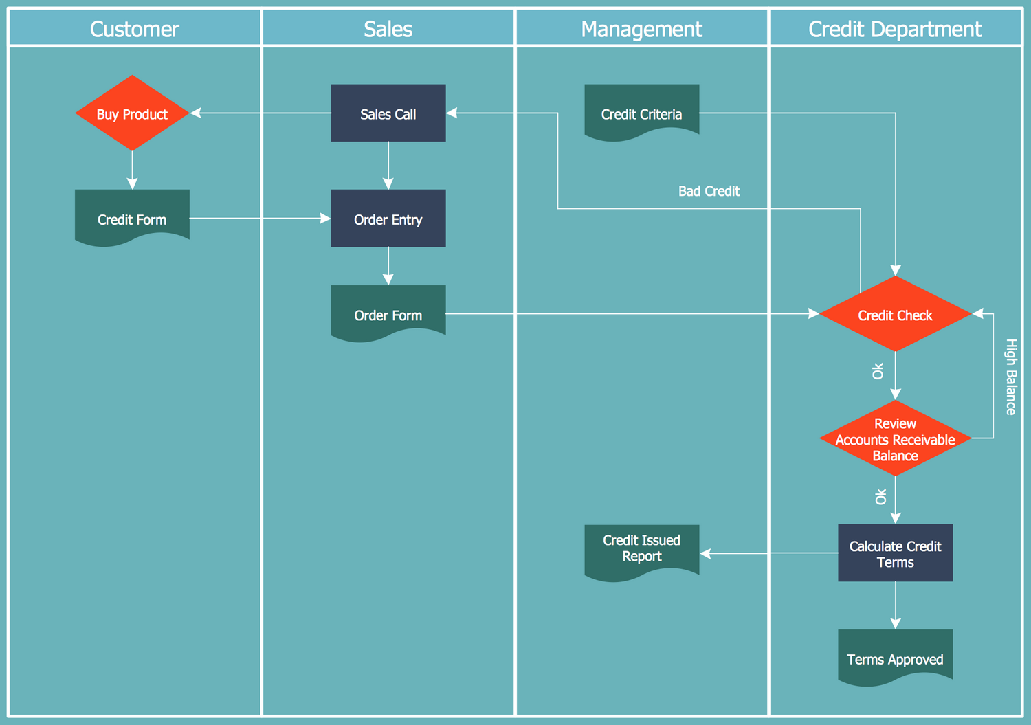
Example 2: Cross-Functional Flowchart — Credit Approval Process
This diagram was created in ConceptDraw DIAGRAM using the "Cross-Functional Flowchart" library from the Cross-Functional Flowcharts solution. An experienced user spent 3 minutes creating this sample.
This Process Flowchart sample shows the credit approval process, which is a process needed to be passed by an individual or a business (debtor or borrower) for receiving permission from the creditor (lender) to take the credit (loan) with defined goal or to pay for the goods or services with delay on a limited period. The credit approval process involves a number of stages and several participants, responsible persons and departments: Customer, Sales, Management, and Credit Department. In connection with the distribution of actions and responsibilities between the participants of a process, the steps are placed at the different swim lanes, that in this case is very convenient, clear and easily readable. You can observe the names of responsible at the caption of the diagram. The ConceptDraw DIAGRAM software and the Process Flowcharts solution, in particular, can effectively help you to construct the Process Flowcharts of any complexity with the aid of ready-made vector objects, cross functional flowchart examples and cross functional flowchart template.
Example 3: Deployment Flowchart — Trading Process Diagram
This diagram was created in ConceptDraw DIAGRAM using the "Cross-Functional Flowchart" library from the Cross-Functional Flowcharts solution. An experienced user spent 20 minutes creating this sample.
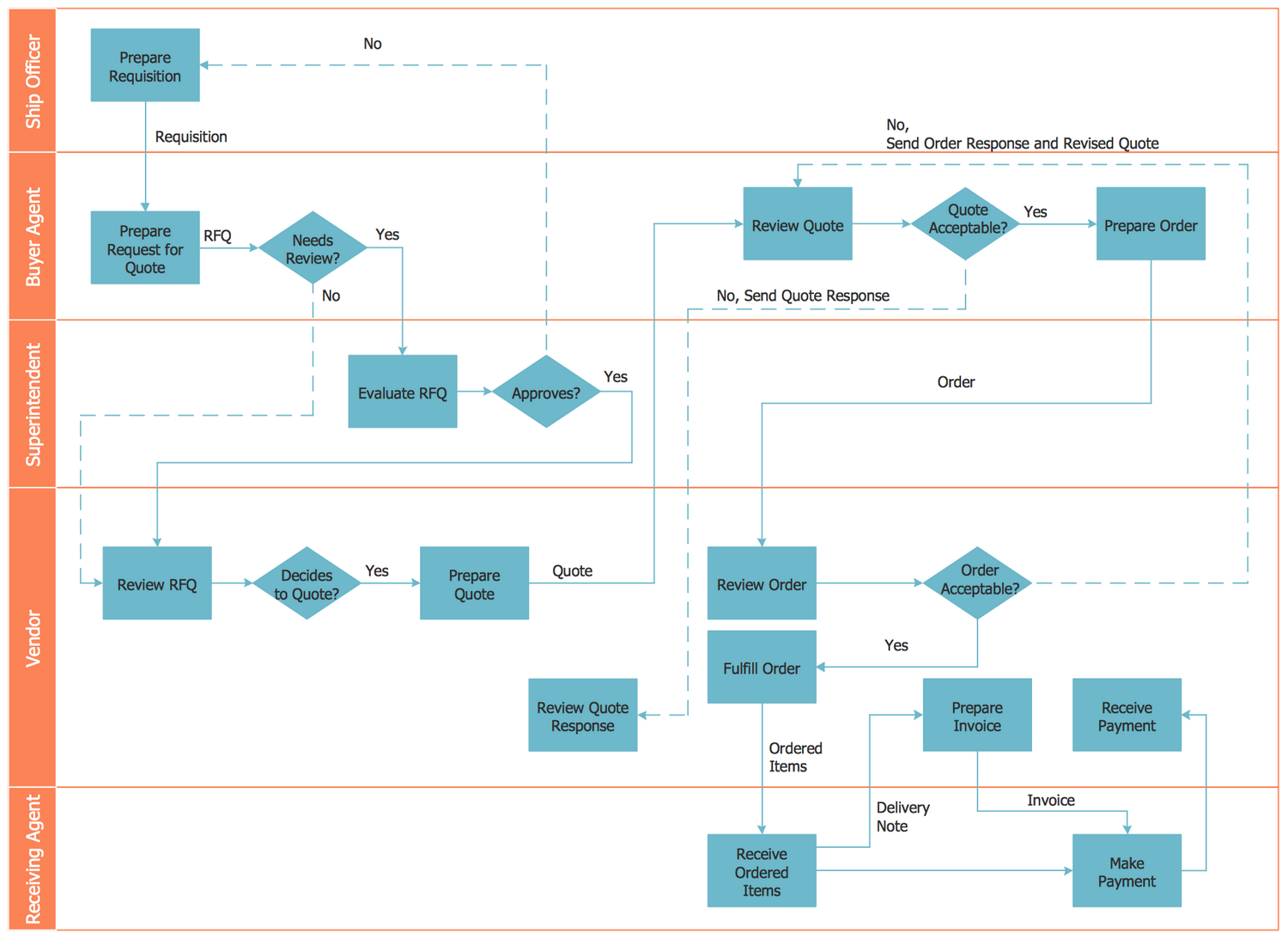
This Cross-Functional Flowchart sample depicts the trading process flow. The trade is a kind of business activity associated with sale and purchase of goods and services. In other words, it is a commerce transaction, when the buyer gets certain goods at the property in return for anything by agreement (money, securities, etc.). The trading process involves the step-by-step execution of the algorithm. It is convenient, when the algorithm is presented in a clear and visually comprehensible view, as in this diagram. The swim lanes positioned horizontally and in a quantity of five, represent Ship Officer, Buyer Agent, Superintended, Vendor, and Receiving Agent. The process steps are represented by rectangular objects. Meeting the diamond object, you need to make a decision and depending on it move in one or another direction. The use of ConceptDraw DIAGRAM connectors to create the Cross-functional flowchart diagrams, Visio cross functional flowchart and Process flowcharts is an intuitive and time-saving solution.
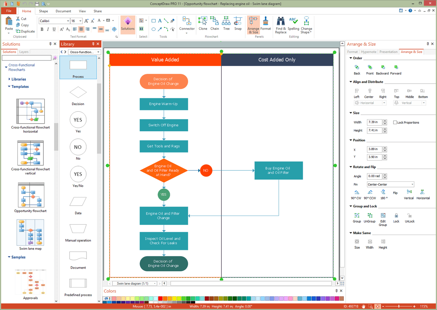
Example 4: Opportunity Flowchart — Replacing Engine Oil
This diagram was created in ConceptDraw DIAGRAM using the "Cross-Functional Flowchart" library from the Cross-Functional Flowcharts solution. An experienced user spent 5 minutes creating this sample.
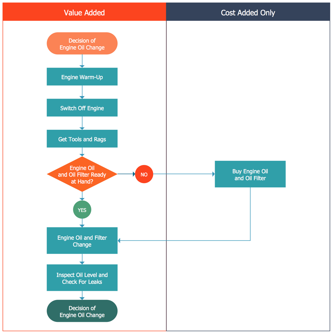
This Opportunity Process Flowchart sample shows the steps involved in a process of replacing the engine oil. The Opportunity Flowcharts are widespread and used in a business process improvement to identify and to optimize the process steps that need be improved. It is a quite simple Flowchart with little quantity of steps, which are represented accurately from the top down and can be passed step-by-step from the Start point when an idea to change the engine oil appears, to the Finish point where is taken decision to change the engine oil. The swim lanes can be placed vertically or horizontally in the flowchart, in this case we have a vertical arrangement. All steps apart one are arranged within a Value Added swim lane, the 'Buy Engine Oil and Oil Filter' step is requiring expenses and placed within a Cost Added swim lane. This example shows a Process Flowchart that can be used for the explanation the process, analysis, re-engineering, presentation or documentation needs.
Example 5: Opportunity flowchart — Order Processing
This diagram was created in ConceptDraw DIAGRAM using the "Cross-Functional Flowchart" library from the Cross-Functional Flowcharts solution. An experienced user spent 15 minutes creating this sample.
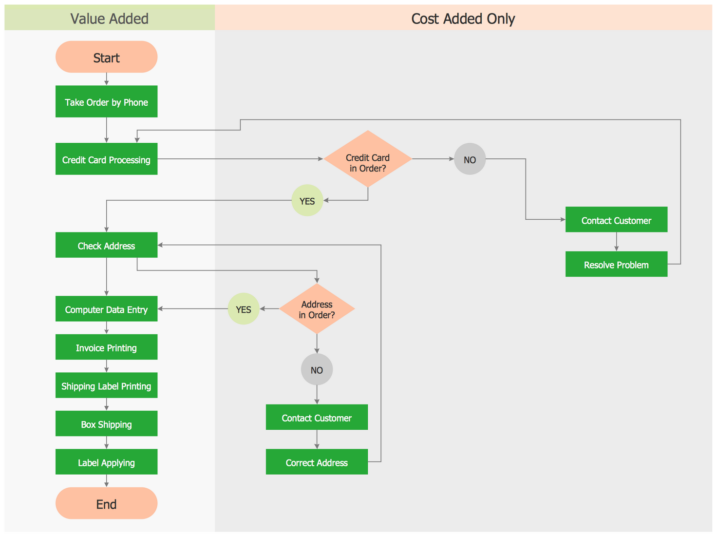
This example shows a Process Workflow diagram describing an order processing flow. There are identified the main steps of the ordering process and represented as a chain on the flowchart, with beginning at the Start point and finishing at the End point. The process steps are divided on the value-added steps and cost-added-only steps, and separated between two corresponding columns. The first ones are the steps used for making the product or service and executed from the top down when everything works ideally, and the second ones represent the actions of checking and fixing problems or inefficiencies. Trying to find the best tool to construct the Process Flowchart, pay your attention to the ConceptDraw DIAGRAM software and powerful tools of the Process Flowcharts solution. This Process Flowchart made the ordering process clear and visible, so it can be successfully used for documenting and analysis, for future automation of the process or any process-building actions inside of the company.
Example 6: Swimlane Process Mapping Diagram — Payroll Process
This diagram was created in ConceptDraw DIAGRAM using the Cross-Functional Flowchart library from the Cross-Functional Flowcharts Solution. An experienced user spent 25 minutes creating this sample.
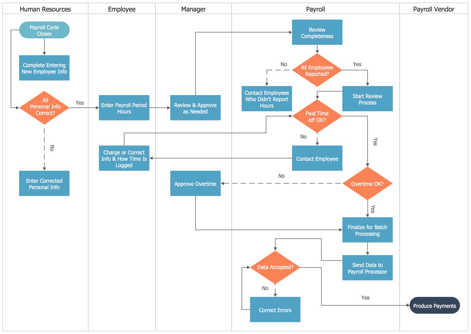
This Swimlane Process Mapping Diagram example shows a payroll process in a clear visual manner so that anyone involved in the process can quickly see which appropriate steps should be taken. The payroll process is a process including several steps and having as the end result the payment salary for the employees. First is realized the accounting of worked hours and overtime for each employee of a given enterprise on the basis of the employees' reports, at this, it is also realized the contacting with employees who didn't report their hours in some reasons. Then, the payment is calculated according to the set rates and finally at the end of each agreed period is produced the payment to the employees with the net of taxes. The process steps are located within the diagram's swim lines Human Resources, Employee, Manager, Payroll, Payroll Vendor. Save your time and efforts using the pre-made vector shapes and connectors from the ConceptDraw's Cross-Functional Flowcharts solution when creating your own Cross functional flow chart.
Example 7: Process Flowchart — CH-1 Diagram
This diagram was created in ConceptDraw DIAGRAM using the CH-1 Symbols library from the Cross-Functional Flowchart solution. An experienced user spent 15 minutes creating this sample.
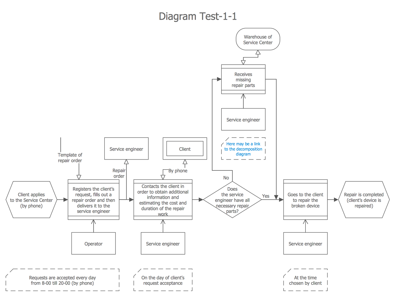
This CH-1 diagram models the business process of repairing the household devices by the service center. This process includes the defined list of steps and particularities, which are represented in the diagram. The repair works are executed at the client’s place after receiving the prior telephone request by a call center operator, which takes calls every day from 8-00 until 20-00. For each request in a writing view is formalized the repair order that is delivered to the corresponding service engineer. He needs to contact with a client to clarify the details of a failure, to estimate the repair cost, to reach an agreement for the suitable time of arrival, to take the needed details on a warehouse and then repair the broken device. This Business Process Flowchart explains all steps in a clear and visual manner using the symbols predefined by the CH-1 notation, and can be used for educational needs or as detailed instruction for workers of a service center.
Example 8: Insurrection Act Flowchart
This diagram was created in ConceptDraw DIAGRAM using the Cross-Functional Flowchart library from the Cross-Functional Flowcharts Solution. An experienced user spent 25 minutes creating this sample.
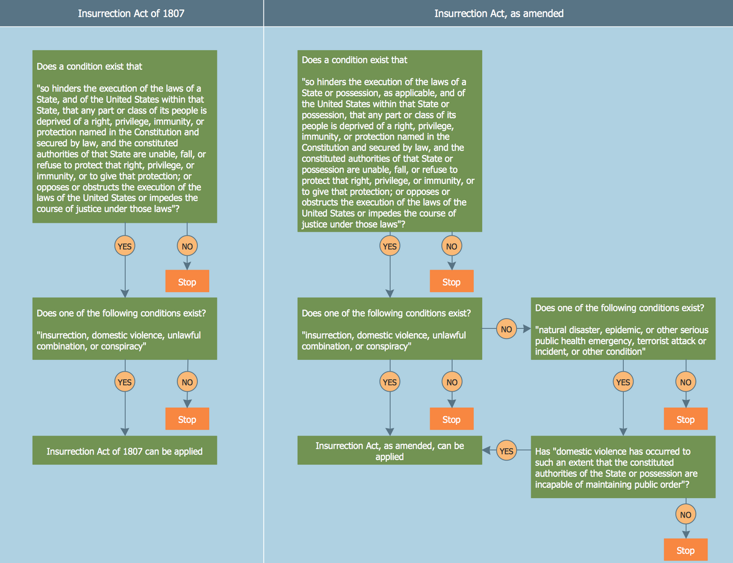
This cross functional flowchart sample demonstrates the Insurrection Act flow designed on the base of the Wikimedia Commons file “Insurrection Act Flowchart.png”. The Insurrection Act adopted in 1807 is the set of laws developed to regulate the authority of the President of USA, to limit its power in deploying troops on the territory of the United States, as well as in questions of quelling the rebellion, lawlessness, and insurrection. The first column represents the provisions of the Insurrection Act of 1807, the second one depicts the amended Insurrection Act. It is convenient to overview both wording (original and amended) placed together on one diagram, such placement easier their comparison. As for the differences in original and amended wording of the Insurrection Act, the Paragraph 2 was significantly extended and contains in addition to such conditions as the insurrection, unlawful combination, domestic violence, conspiracy, also the natural disaster, epidemic and other serious public health emergency, terrorist attack or incident, and other conditions.
Example 9: Investment Management Process
This diagram was created in ConceptDraw DIAGRAM using the Cross-Functional Flowchart library from the Cross-Functional Flowcharts Solution. An experienced user spent 25 minutes creating this sample.
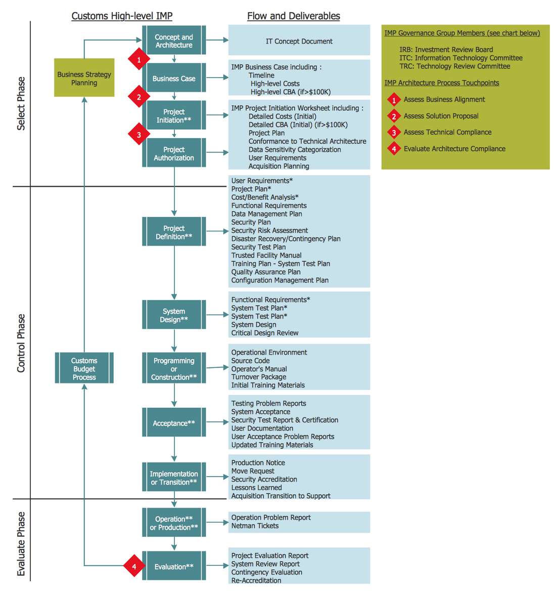
This cross functional diagram sample describes the investment management process flow. It was constructed on the base of the Wikimedia Commons file "Investment Management Process Example.jpg" by means of ConceptDraw's Cross-Functional Flowcharts solution tools. The investment management or financial management is the management of all aspects of investment activities, including the management of various securities and other assets, such as shares, bonds, real estate, etc. in order to meet the defined investment goals for the benefits of the investors. The investment management process contains three main phases: selection, control, and evaluation. The Select phase suggests the process of business strategy planning and includes four steps: concept and architecture, business case, project initiation, project authorization. The Control phase is a process of controlling the custom budget that includes the steps of project definition, system design, programming or construction, acceptance, implementation or transition. The Evaluate phase contains the steps of operation or production, and evaluation of the project's success or failure.
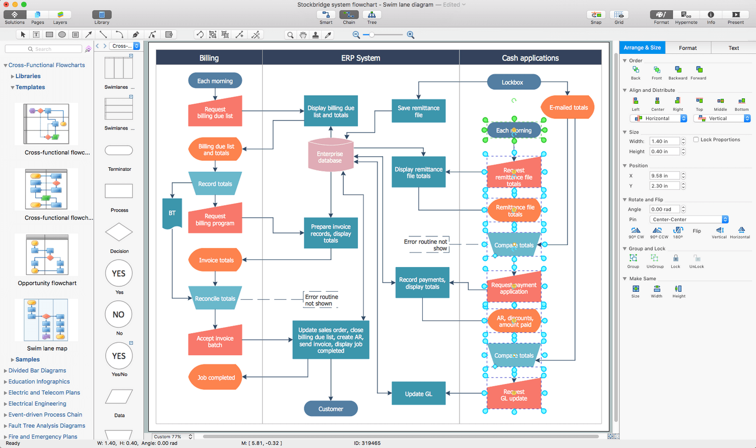
Example 10: Stockbridge System Flowchart
This diagram was created in ConceptDraw DIAGRAM using the Cross-Functional Flowchart library from the Cross-Functional Flowcharts Solution. An experienced user spent 25 minutes creating this sample.
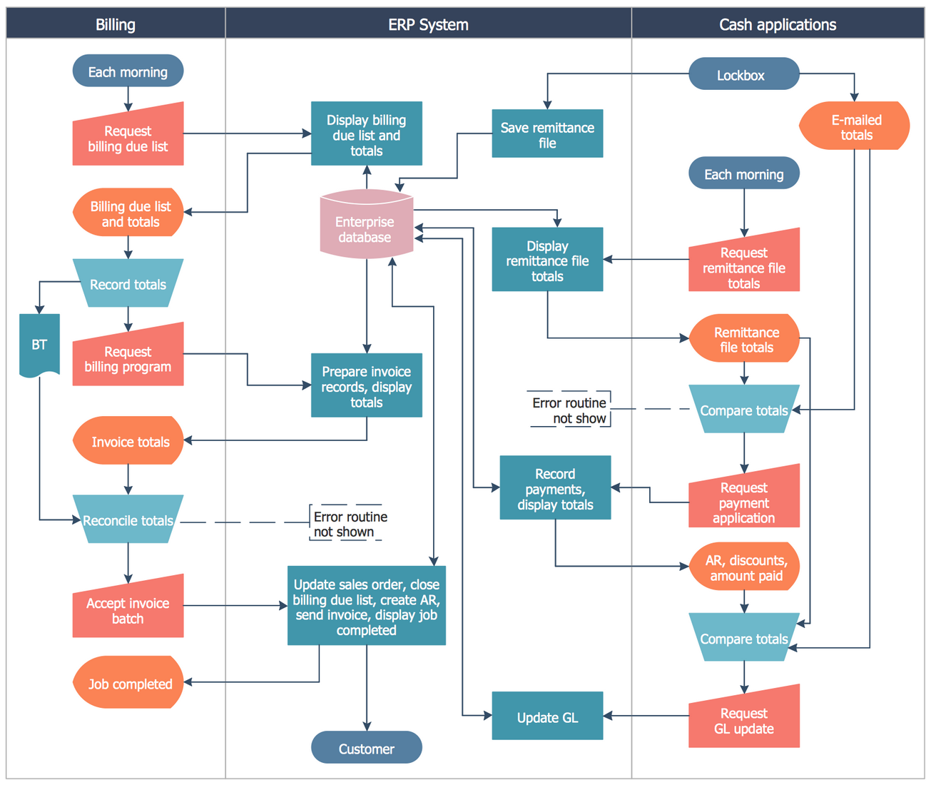
This cross-functional flowchart sample demonstrates the Stockbridge system operation flow. Being designed on the base of the Wikimedia Commons file "Stockbridge system flowchart example.jpg" this flowchart represents the data processing system that combines the manual and computerized processing to handle accounts receivable, billing, and general ledger. The data processing system excellently combines the people, machines, and processes, and produces the defined sets of outputs for the sets of inputs that can be as different kinds of information, as data, facts, etc. The data processing system can convert data to another form or language, realize the validation of data, their sorting, summarization, aggregation, analysis, and reporting. This is a complex flowchart including three swimlanes: Billing, ERP system, and Cash applications, and contains many interconnected steps. At the Billing column, you can see that the process starts 'each morning' by the 'request billing due list' step, at the Cash applications column you can observe the flow beginning 'each morning' by the 'request remittance file totals'.
Inside
What I Need to Get Started
Both ConceptDraw DIAGRAM diagramming and drawing software and the Cross-Functional Flowcharts solution can help creating the business processes diagrams you need. The Cross-Functional Flowcharts solution can be found in the Business Processes area of ConceptDraw STORE application that can be downloaded from this site. Make sure that both ConceptDraw DIAGRAM and ConceptDraw STORE applications are installed on your computer before you get started.
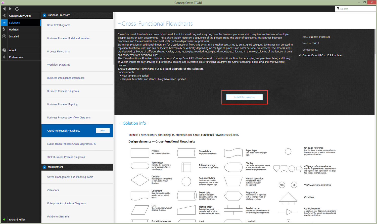
How to install
After ConceptDraw STORE and ConceptDraw DIAGRAM are downloaded and installed, you can install the Cross-Functional Flowcharts solution from the ConceptDraw STORE.
Start using
To make sure that you are doing it all right, use the pre-designed symbols from the stencil libraries from the solution to make your drawings look smart and professional. Also, the pre-made examples from this solution can be used as drafts so your own drawings can be based on them. Using the samples, you can always change their structures, colors and data.
Cross-Functional Flowcharts
The humble flowchart is one of the more ubiquitous diagrams used when constructing or analyzing business processes. Their simple nature makes them an ideal candidate for use as a solution model to a given problem; possible subject matter is practically limitless, and they can be utilized and understood by all levels of employee throughout a company.
The basic building blocks of a flowchart are always the same — the starting and (sometimes multiple) ending points of the process flow are called 'terminals', and are shown as circles, ovals, stadiums or rounded rectangles. Decisions are described within diamond shapes, and all are connected with arrowed lines that represent the flow of control throughout the process.
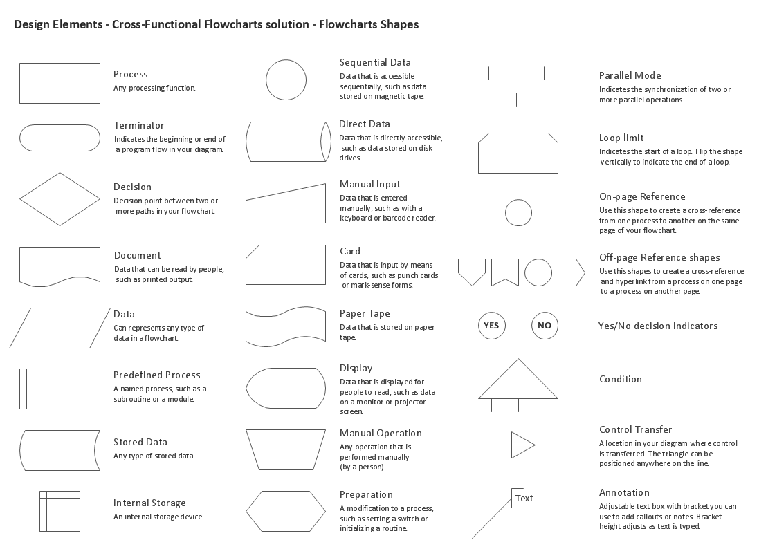
Design elements from ConceptDraw DIAGRAM 's Cross-Functional Flowcharts solution, showcasing some of the specialized icons available, and describing their usage
It is possible to add extra layers of complexity, by utilizing specialist shapes for certain tasks, or go even further by adding what's known as 'swimlanes' — turning a flowchart into a cross-functional flowchart (also known as a swimlane diagram or deployment flowchart). A normal flowchart is a basic view of the steps in a process — by adding swimlanes, that process can then be segregated depending on which of an organization's departments is responsible for certain steps.
For instance, a credit approval process can be divided into steps taken by a customer, then the sales team, actions issued by management, and finally any steps taken by the credit department.
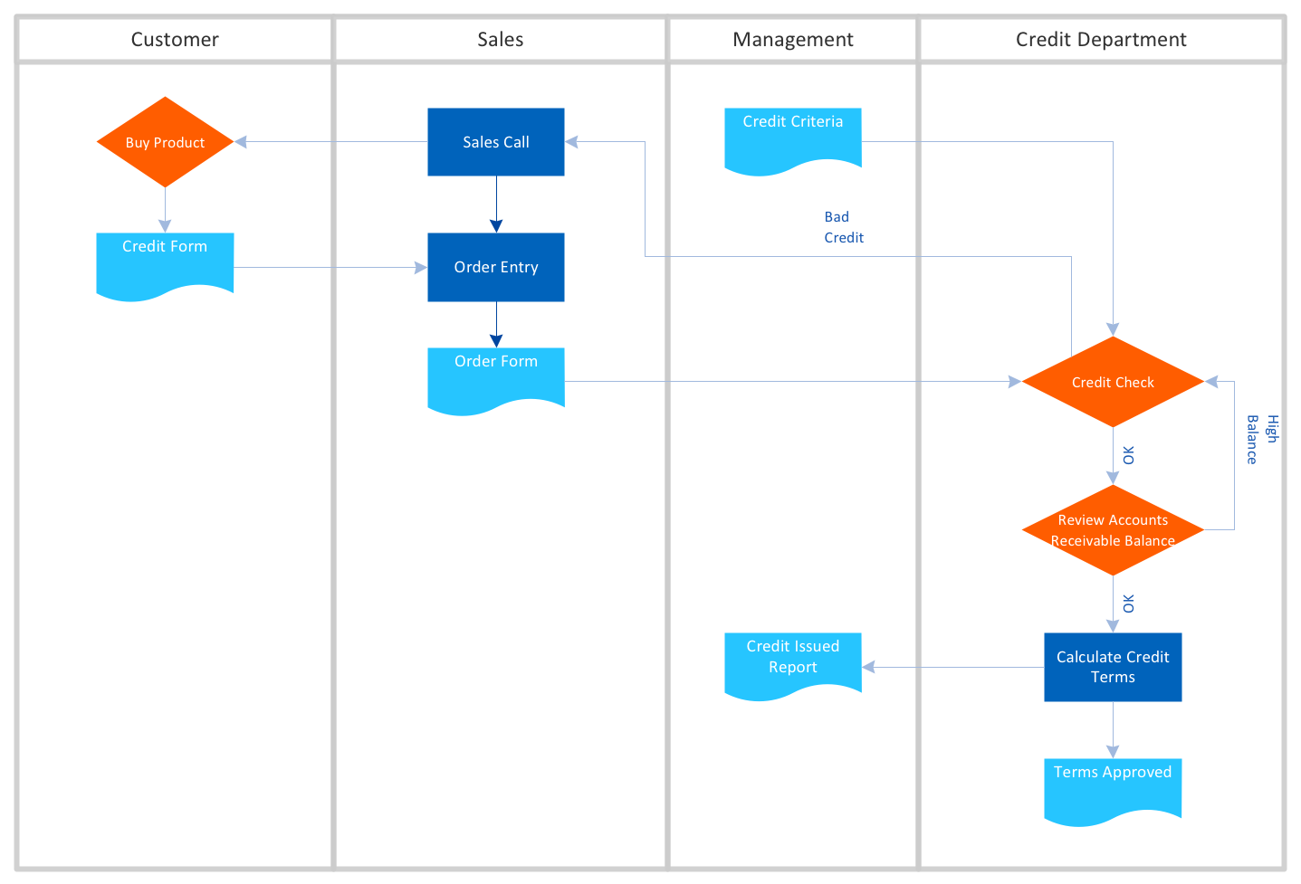
A credit approval system designed using ConceptDraw DIAGRAM, with swimlanes arranged vertically
Swimlanes can be arranged horizontally or vertically — the choice is generally just an aesthetic one, although horizontal lanes are typically more useful when viewing through a computer monitor.
Essentially a cross-functional diagram allows you to take a look at processes with a wider scope than otherwise possible, and with more precision. Business process mapping using this technique enables knowledge workers to depict a company in its entirety, including all departments and even external influences such as customers or resources. This can be useful for stakeholders and upper management to have an at-a-glance perspective of their business, that clearly defines roles and responsibilities. Deployment diagrams can also be a collaborative tool, allowing stakeholders to plan resource allocation, and re-assign it if necessary.
From a quality management perspective, since each department of an organization can be included in a diagram, it makes it easier to identify areas where efficiency or productivity is lacking, and figure out the root cause — perhaps some problem with materials in manufacturing, or a case of employees within a certain sector not performing adequately. The process itself can be studied as a whole, and unnecessary steps filtered out.
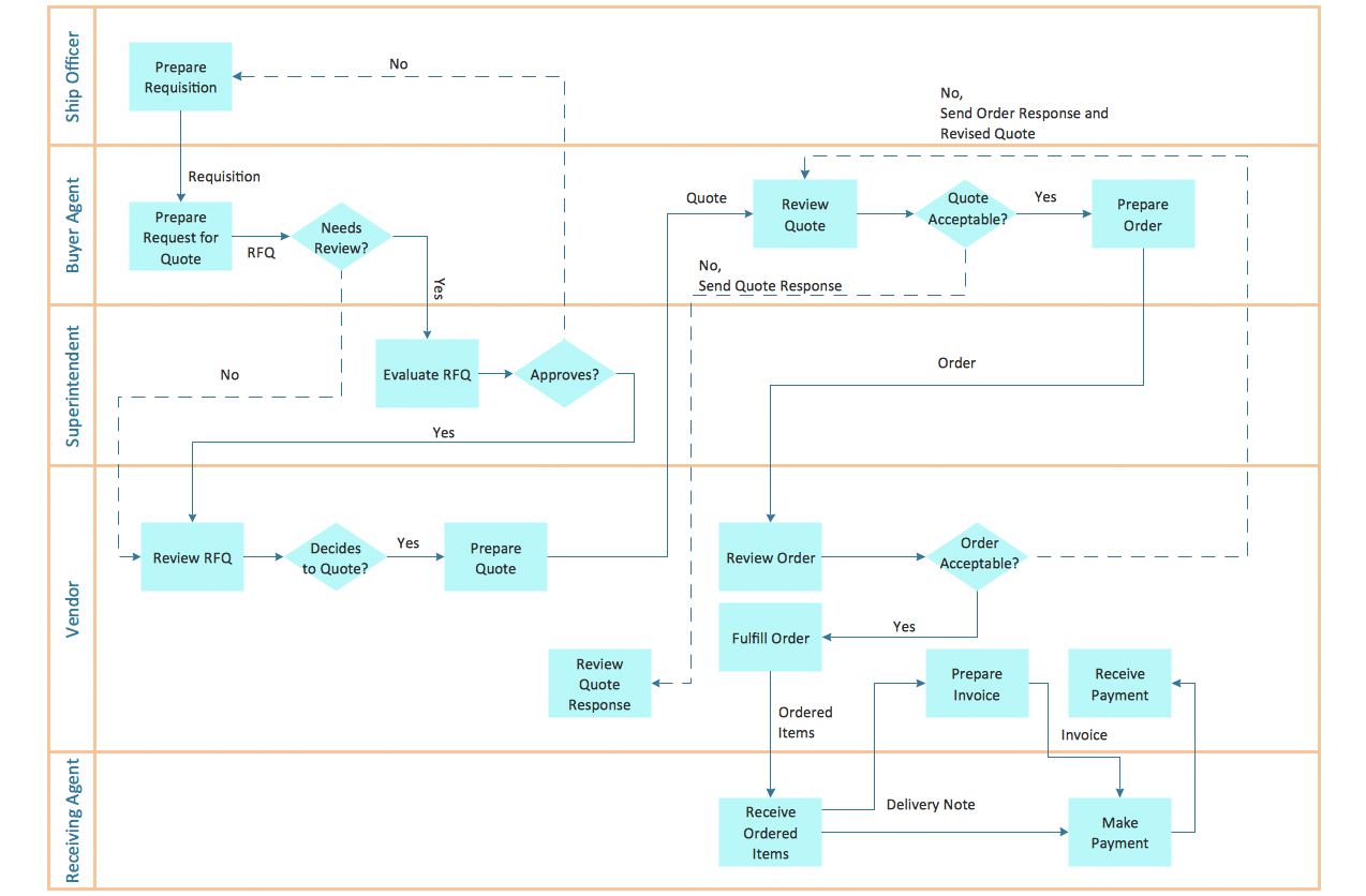
ConceptDraw DIAGRAM was used to create this diagram of a trading process, with the swimlanes arranges horizontally
ConceptDraw DIAGRAM is an example of the sort of diagramming software that offers a comprehensive selection of tools and solutions to make designing your own cross-functional flowchart a quick and simple task. With add-on solutions such as Flowcharts, Business Process Mapping, and Cross-Functional Flowcharts, ConceptDraw users are provided with a whole host of icon libraries, samples and templates that do the all groundwork necessary to assist in creating professional diagrams that are beneficial to the workforce.
The RapidDraw functionality inherent in ConceptDraw DIAGRAM makes the task even easier — flowchart steps can be created with a single click, automatically triggering the next step in a process, using a logical algorithm to align themselves on the page in the most effective manner. For an extra resource, the ConceptDraw website also provides an invaluable selection of tutorial videos and FAQs that assist with any technical questions.
ConceptDraw DIAGRAM, with its cross-functional flowchart based solutions, is an all-in-one resource for displaying and analyzing business processes, quality controls, and departmental responsibilities.
