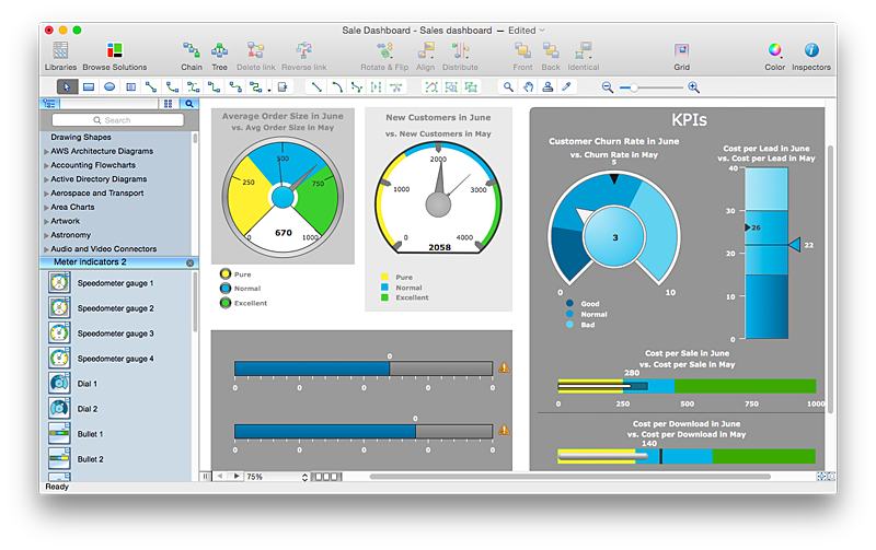
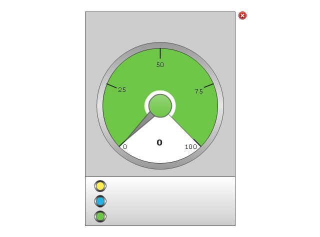
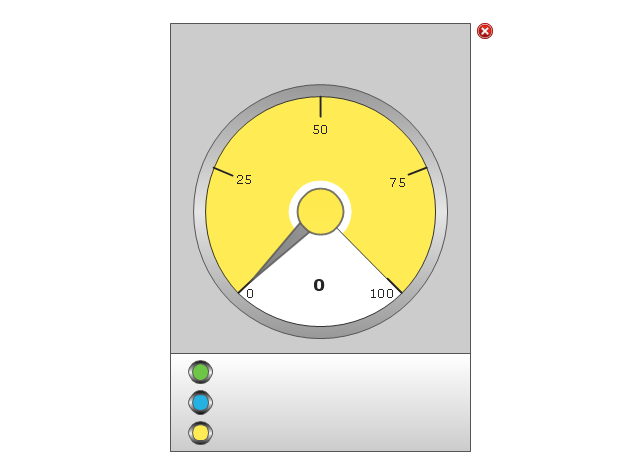
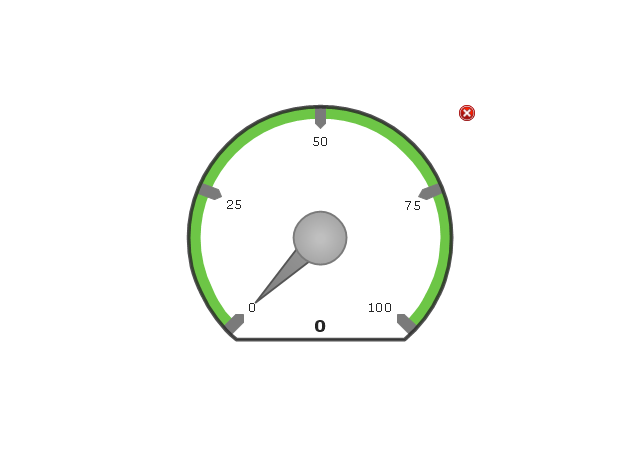
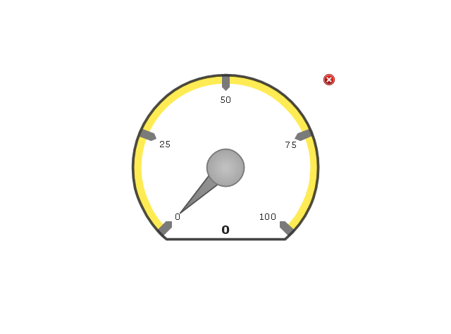
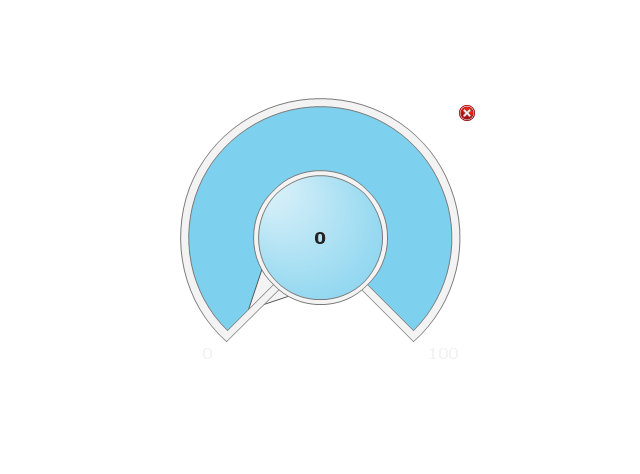
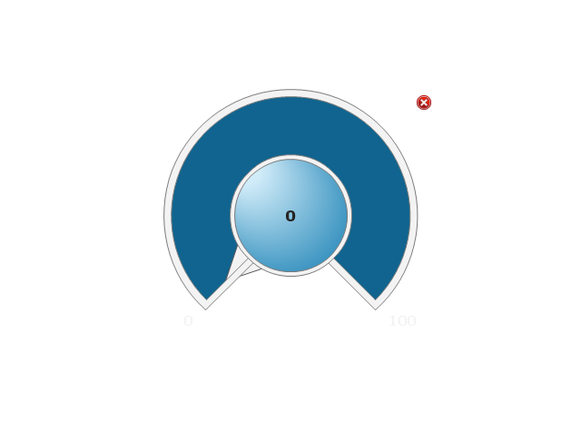
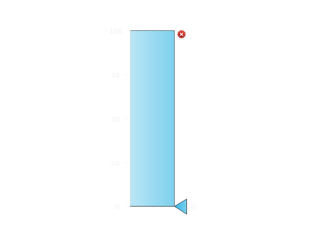
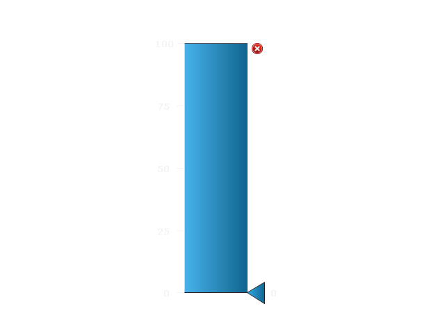
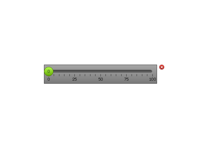
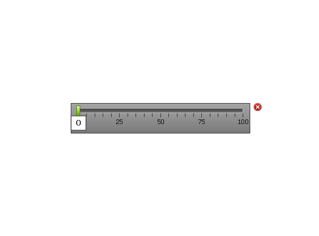
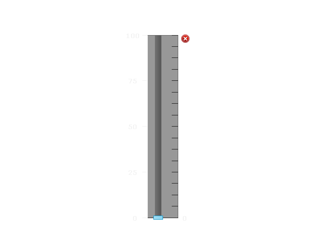
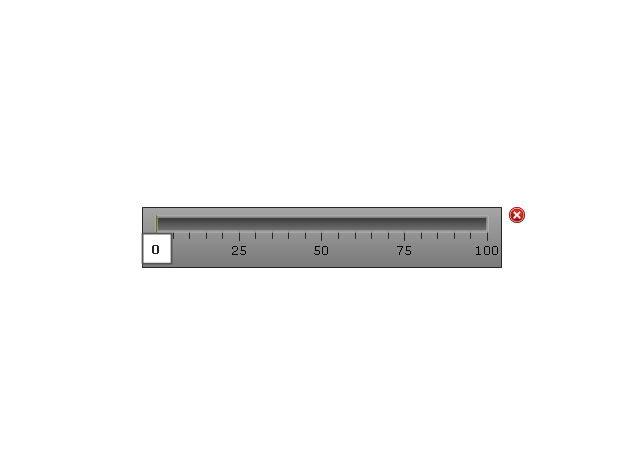
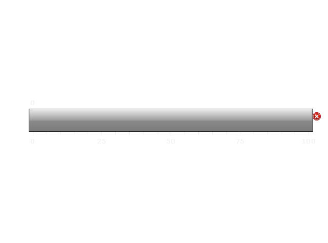
The vector stencils library "Meter indicators 2" (for dark background) contains 29 Live Objects: speedometer gauge, dial, bullet, slider and level meter visual indicators.
The Live Objects designed to display actual measures of performance metrics from external data source files. Some of them also display comparative measures, and colored zones of qualitative ranges with legend.
Use this library to create visual dashboards in the ConceptDraw PRO diagramming and vector drawing software extended with the Meter Dashboard solution from the area "What is a Dashboard" of ConceptDraw Solution Park.
"In association football, the formation describes how the players in a team are positioned on the pitch. Different formations can be used depending on whether a team wishes to play more attacking or defensive football. ...
The WM system was created in the mid-1920s by Herbert Chapman of Arsenal to counter a change in the offside law in 1925. The change had reduced the number of opposition players that attackers needed between themselves and the goal-line from three to two. This led to the introduction of a centre-back to stop the opposing centre-forward, and tried to balance defensive and offensive playing. The formation became so successful that by the late-1930s most English clubs had adopted the WM. Retrospectively, the WM has either been described as a 3–2–5 or as a 3–4–3, or more precisely a 3–2–2–3 reflecting the letters which symbolised it. The gap in the centre of the formation between the two wing halves and the two inside forwards allowed Arsenal to counter-attack effectively. The W-M was subsequently adapted by several English sides, but none could apply it in quite the same way Chapman had. This was mainly due to the comparative rarity of Alex James in the English game. He was one of the earliest playmakers in the history of the game, and the hub around which Chapman's Arsenal revolved." [Formation (association football). Wikipedia]
The diagram example "Association football (soccer) formation 3-2-5 (WM)" was created using the ConceptDraw PRO diagramming and vector drawing software extended with the Football solution from the Sport area of ConceptDraw Solution Park.
www.conceptdraw.com/ solution-park/ sport-soccer
2 Circle Venn Diagram. Venn Diagram Example
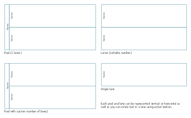
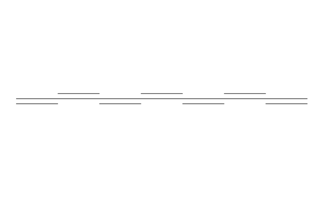
Using the ready-to-use predesigned objects, samples and templates from the Venn Diagrams Solution for ConceptDraw PRO you can create your own professional looking Venn Diagrams quick and easy.The vector stencils library "Swimlanes BPMN1.2" contains 8 swimlane shapes for drawing business process diagrams (BPMN 1.2) using the ConceptDraw PRO diagramming and vector drawing software.
"Swim lanes are a visual mechanism of organising and categorising activities, based on cross functional flowcharting, and in BPMN consist of two types:
(1) Pool.
Represents major participants in a process, typically separating different organisations. A pool contains one or more lanes (like a real swimming pool). A pool can be open (i.e., showing internal detail) when it is depicted as a large rectangle showing one or more lanes, or collapsed (i.e., hiding internal detail) when it is depicted as an empty rectangle stretching the width or height of the diagram.
(2) Lane.
Used to organise and categorise activities within a pool according to function or role, and depicted as a rectangle stretching the width or height of the pool. A lane contains the flow objects, connecting objects and artifacts." [Business Process Model and Notation. Wikipedia]
The example "Design elements - Swimlanes BPMN1.2" is included in the Business Process Diagram solution from the Business Processes area of ConceptDraw Solution Park.
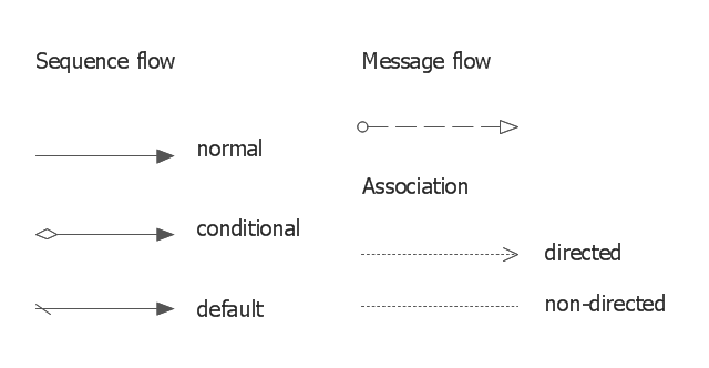
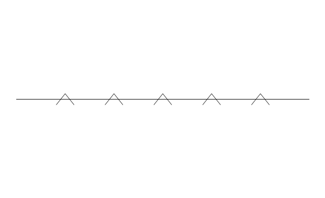
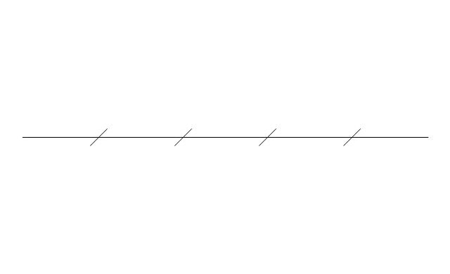
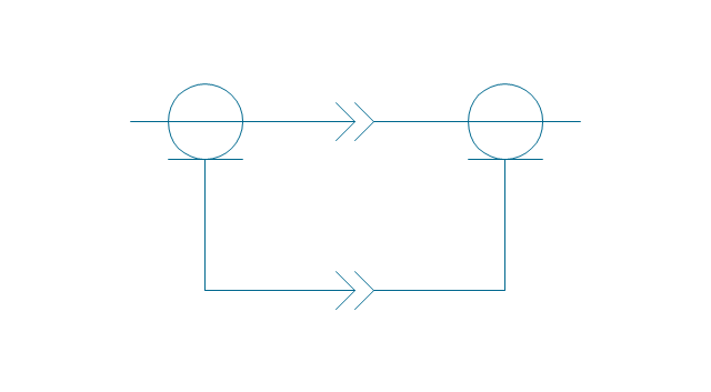
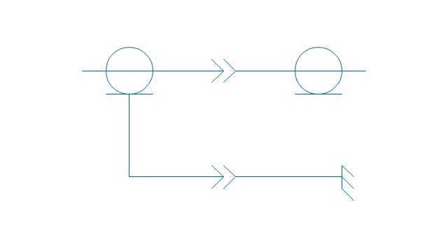
The vector stencils library "Connections BPMN1.2" contains 6 connection symbols of sequence flow, message flow, and association.
Use these shapes for drawing business process diagrams (BPMN 1.2) using the ConceptDraw PRO diagramming and vector drawing software.
"Connections.
Flow objects are connected to each other using Connecting objects, which are of three types: sequences, messages, and associations.
(1) Sequence Flow.
A Sequence Flow is represented with a solid line and arrowhead, and shows in which order the activities are performed. The sequence flow may also have a symbol at its start, a small diamond indicates one of a number of conditional flows from an activity, while a diagonal slash indicates the default flow from a decision or activity with conditional flows.
(2) Message Flow.
A Message Flow is represented with a dashed line, an open circle at the start, and an open arrowhead at the end. It tells us what messages flow across organizational boundaries (i.e., between pools). A message flow can never be used to connect activities or events within the same pool.
(3) Association.
An Association is represented with a dotted line. It is used to associate an Artifact or text to a Flow Object, and can indicate some directionality using an open arrowhead (toward the artifact to represent a result, from the artifact to represent an input, and both to indicate it is read and updated). No directionality is used when the Artifact or text is associated with a sequence or message flow (as that flow already shows the direction)." [Business Process Model and Notation. Wikipedia]
The example "Design elements - Connections BPMN1.2" is included in the Business Process Diagram solution from the Business Processes area of ConceptDraw Solution Park.
"In association football, the formation describes how the players in a team are positioned on the pitch. Different formations can be used depending on whether a team wishes to play more attacking or defensive football. ...
The 2–3–5 was originally known as the "Pyramid", with the numerical formation being referenced retrospectively. ...
For the first time, a balance between attacking and defending was reached. When defending, the two defenders (fullbacks), would watch out for the opponent's wingers (the outside players in the attacking line), while the midfielders (halfbacks) would watch for the other three forwards.
The centre halfback had a key role in both helping to organise the team's attack and marking the opponent's centre forward, supposedly one of their most dangerous players.
It was this formation which gave rise to the convention of shirt numbers." [Formation (association football). Wikipedia]
The diagram example "Association football (soccer) formation 2–3–5 (pyramid)" was created using the ConceptDraw PRO diagramming and vector drawing software extended with the Football solution from the Sport area of ConceptDraw Solution Park.
www.conceptdraw.com/ solution-park/ sport-soccer
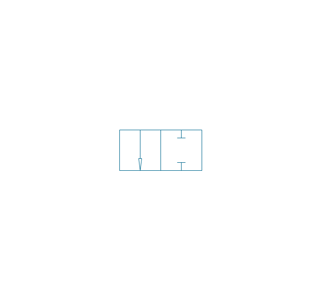
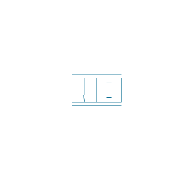
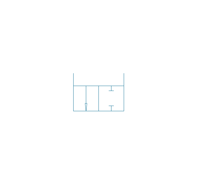
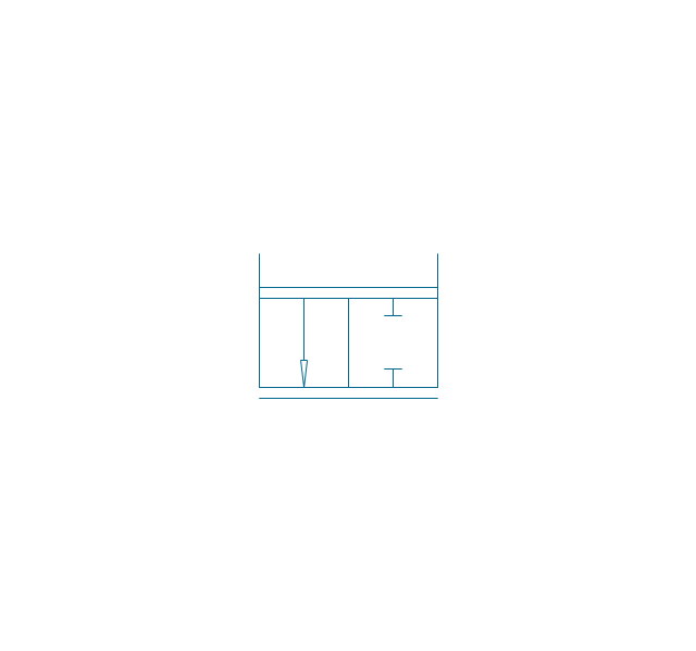
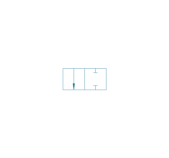
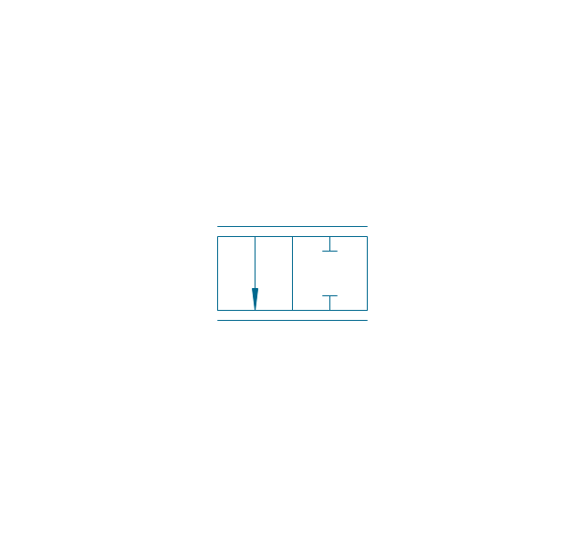
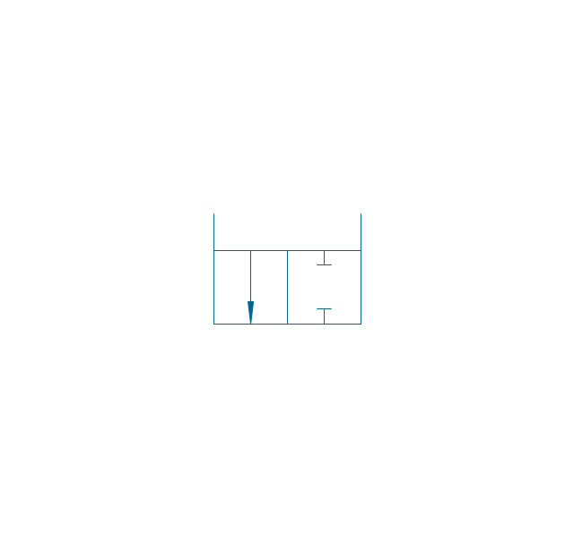
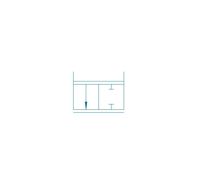
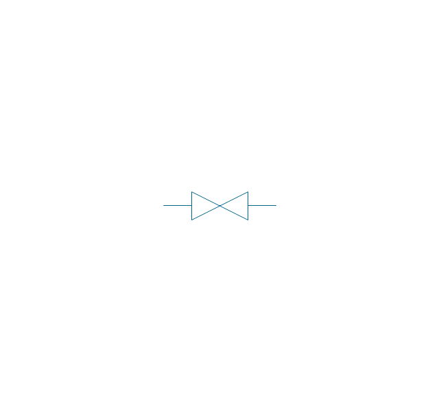
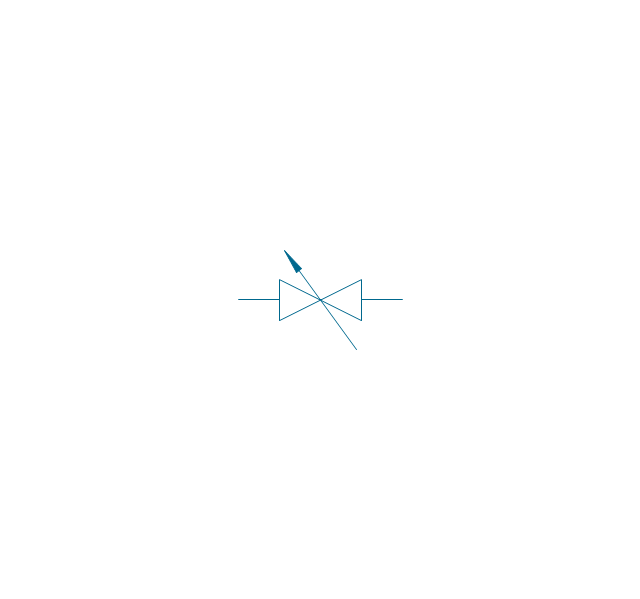
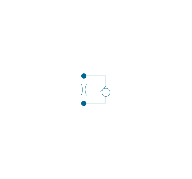
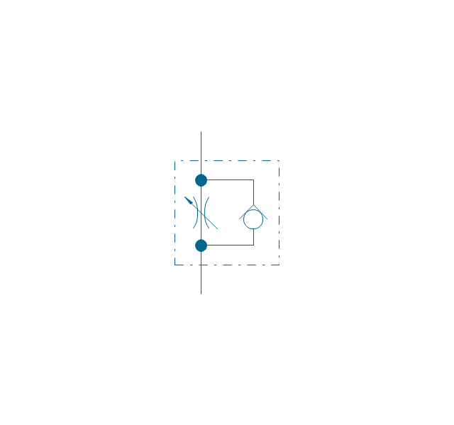
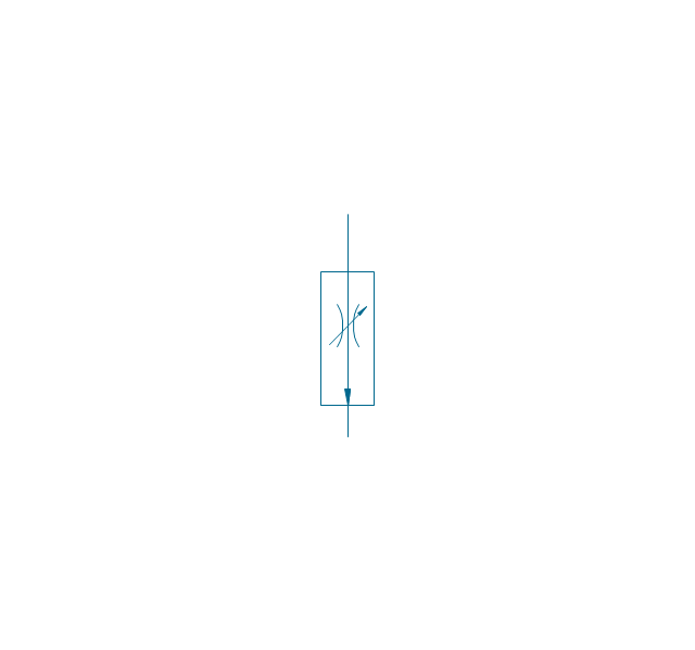
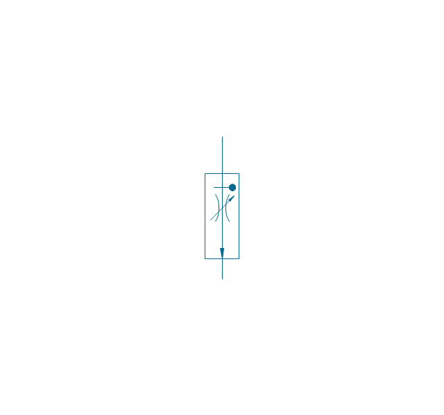
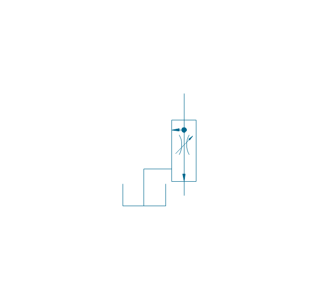
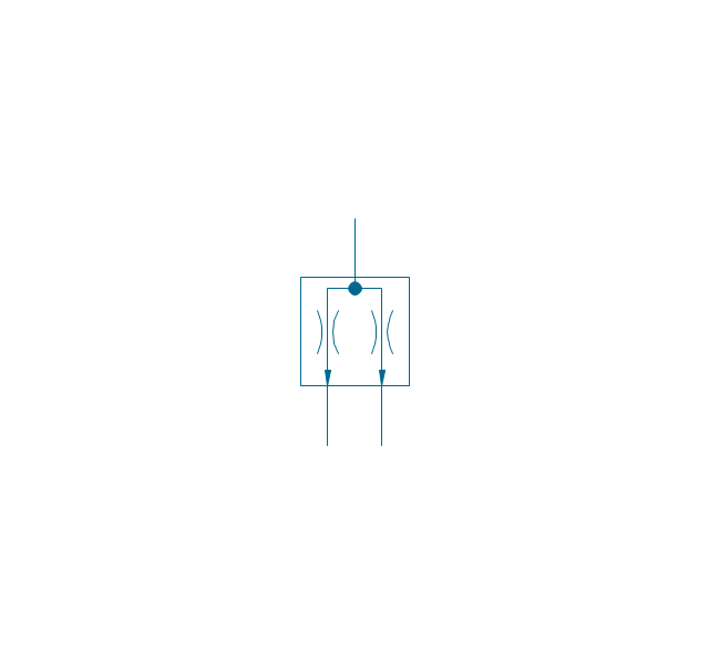
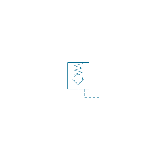
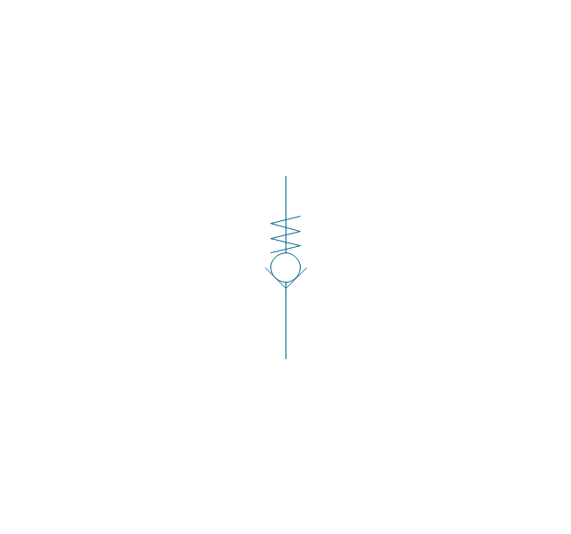
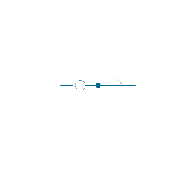
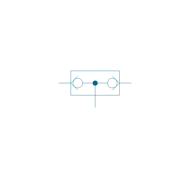
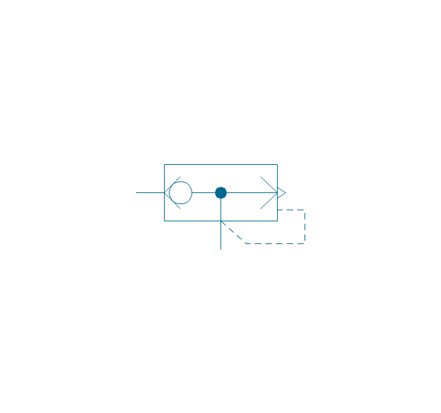
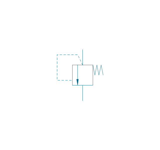
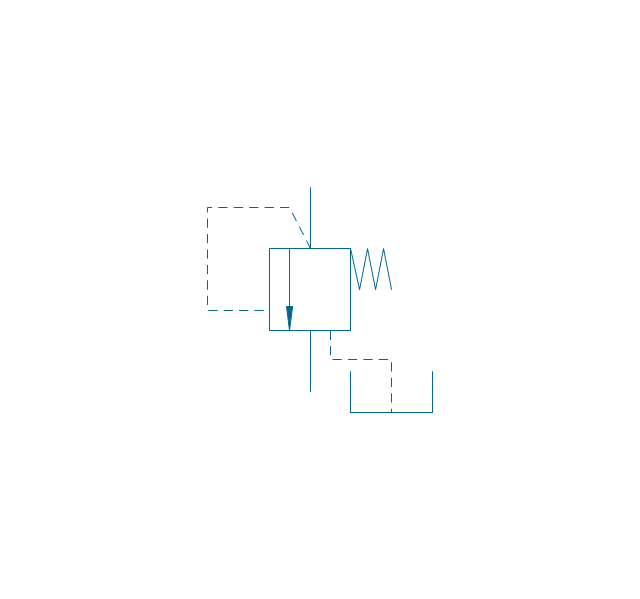
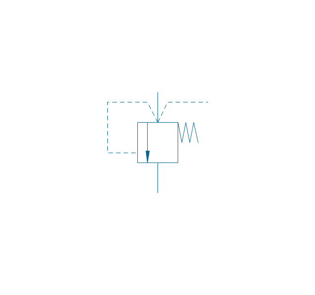
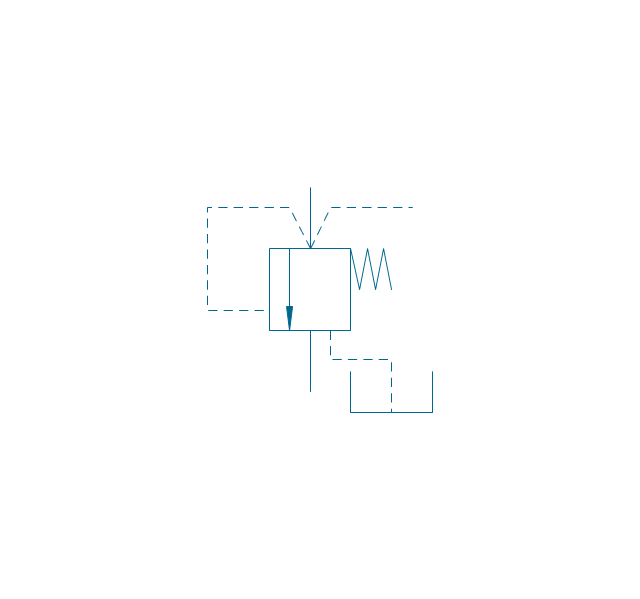
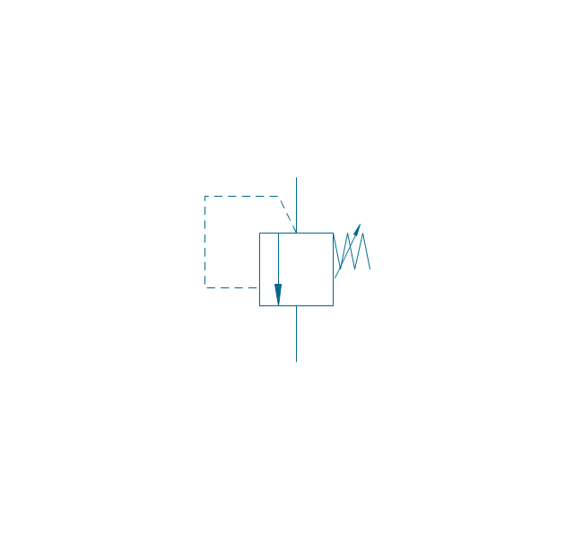
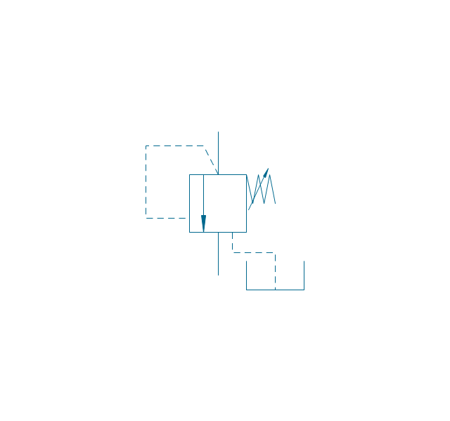
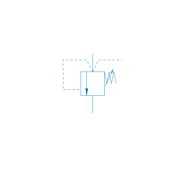
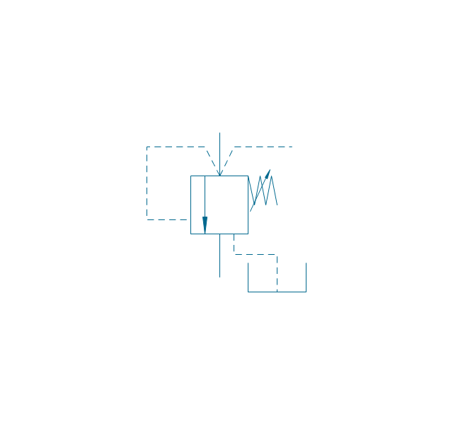
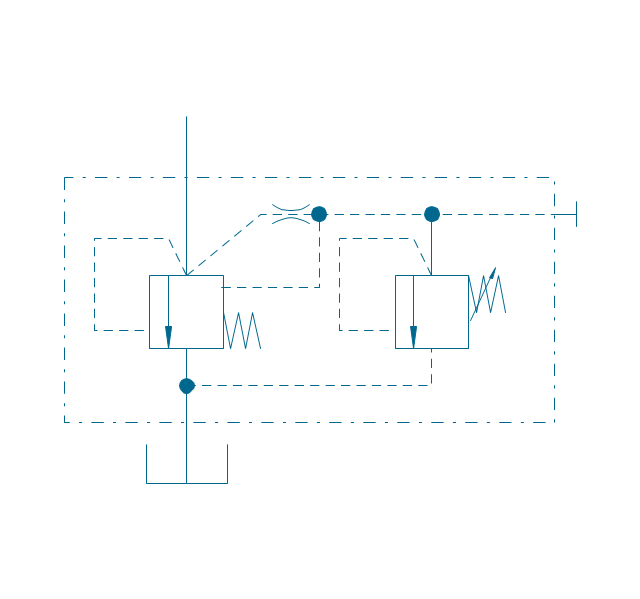
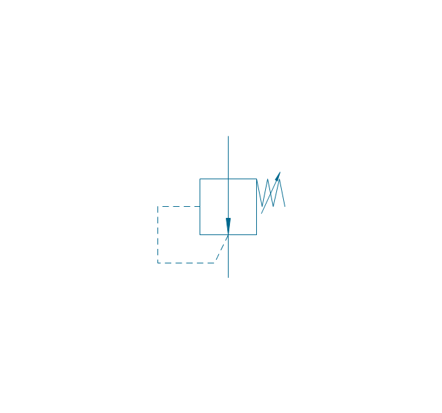
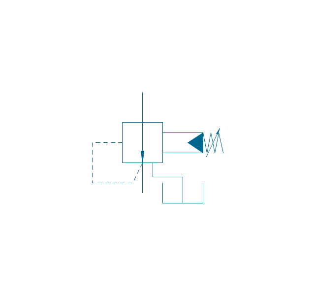
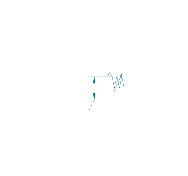
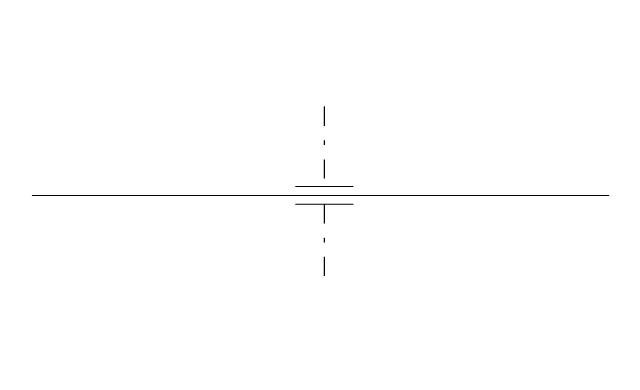
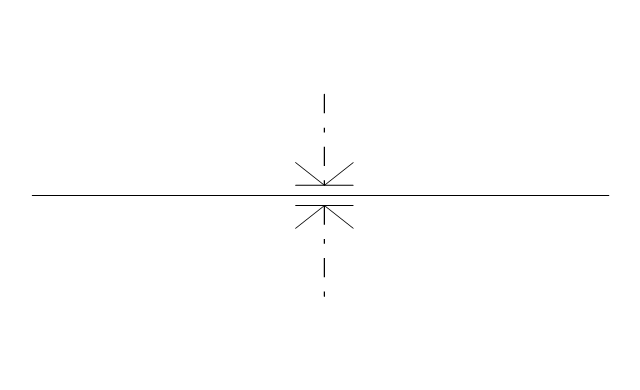
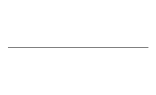
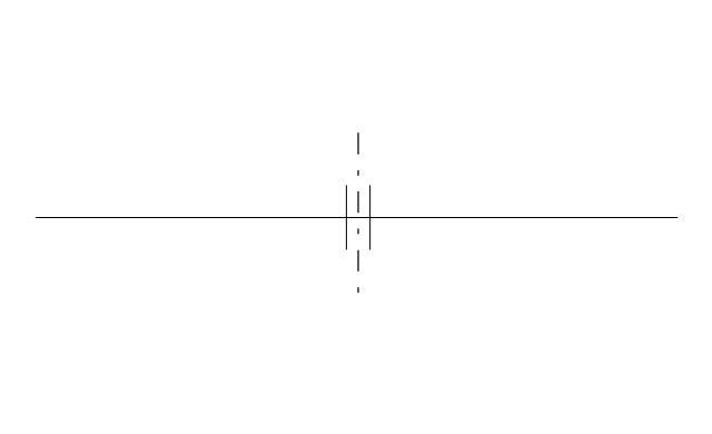
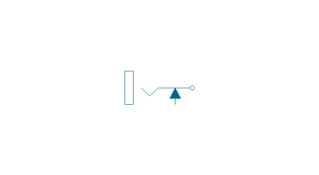
The vector stencils library "Fluid power valves" contains 93 symbols of pre-made hydraulic and pneumatic valves, including directional control valves, flow control valves, pressure control valves, and electrohydraulic and electropneumatic valves.
Use these shapes to design fluid power diagrams in the ConceptDraw PRO diagramming and vector drawing software extended with the Mechanical Engineering solution from the Engineering area of ConceptDraw Solution Park.
www.conceptdraw.com/ solution-park/ engineering-mechanical
Use these shapes to design fluid power diagrams in the ConceptDraw PRO diagramming and vector drawing software extended with the Mechanical Engineering solution from the Engineering area of ConceptDraw Solution Park.
www.conceptdraw.com/ solution-park/ engineering-mechanical
"In computer networking, cloud computing is computing that involves a large number of computers connected through a communication network such as the Internet, similar to utility computing. ...
Network-based services, which appear to be provided by real server hardware, and are in fact served up by virtual hardware, simulated by software running on one or more real machines are often called cloud computing. Such virtual servers do not physically exist and can therefore be moved around and scaled up or down on the fly without affecting the end user, somewhat like a cloud becoming larger or smaller without being a physical object. ...
Typically, the seller has actual energy-consuming servers which host products and services from a remote location, so end-users don't have to; they can simply log on to the network without installing anything. The major models of cloud computing service are known as software as a service, platform as a service, and infrastructure as a service. These cloud services may be offered in a public, private or hybrid network. Google, Amazon,leadsquared.com, Oracle Cloud, Salesforce, Zoho, Access2MyPC, and Microsoft Azure are some well-known cloud vendors." [Cloud computing. Wikipedia]
The AWS architecture diagram example "2-Tier Auto-scalable Web Application Architecture in 1 AZ" was created using the ConceptDraw PRO diagramming and vector drawing software extended with the AWS Architecture Diagrams solution from the Computer and Networks area of ConceptDraw Solution Park.
The vector stencils library "Pipes 2" contains 48 symbols of pipes.
Use it for drawing plumbing and piping building plans, schematic diagrams, blueprints, or technical drawings of waste water disposal systems, hot and cold water supply systems in the ConceptDraw PRO diagramming and vector drawing software extended with the Plumbing and Piping Plans solution from the Building Plans area of ConceptDraw Solution Park.
www.conceptdraw.com/ solution-park/ building-plumbing-piping-plans
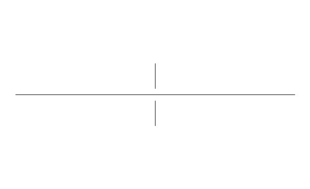
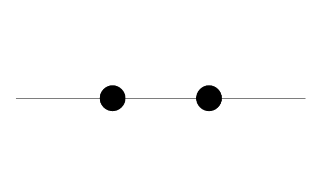
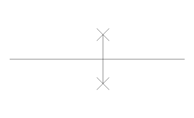
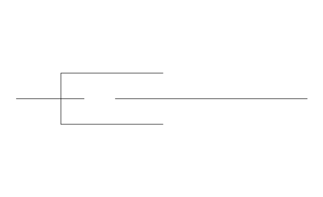
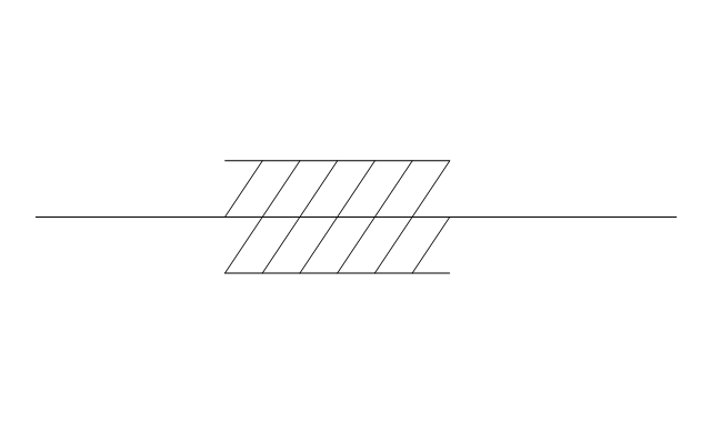
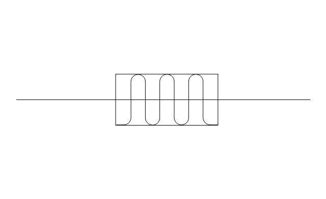
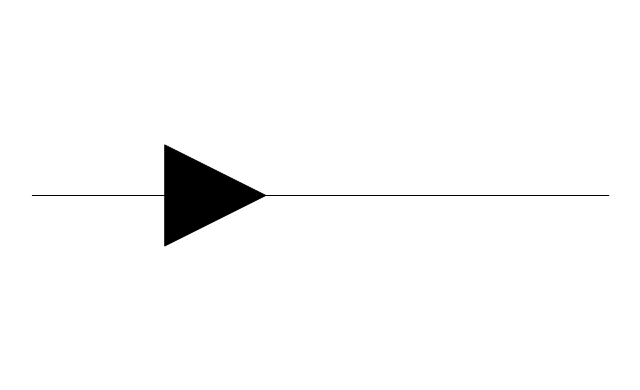
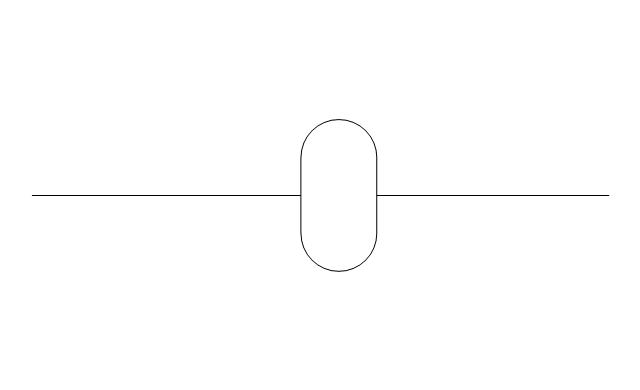
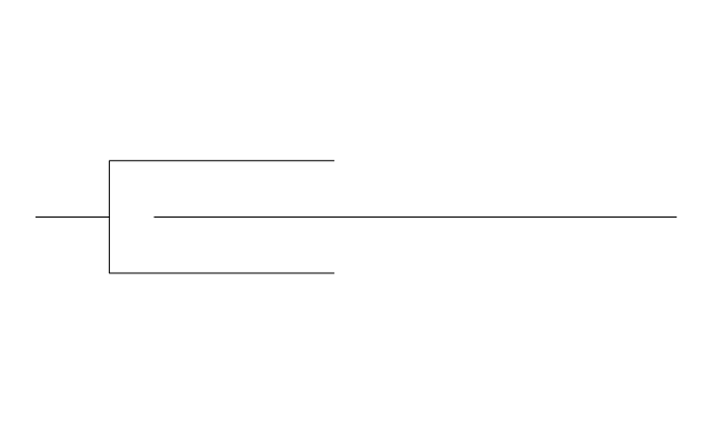
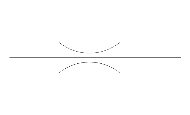
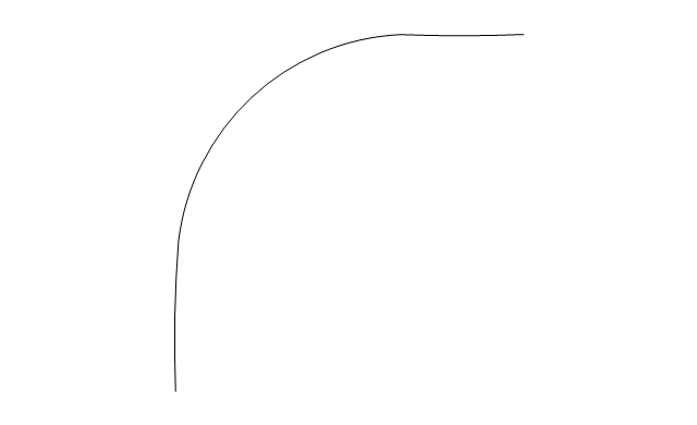
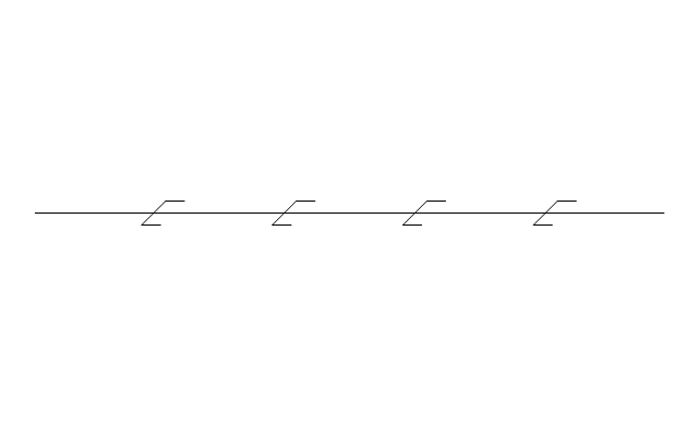
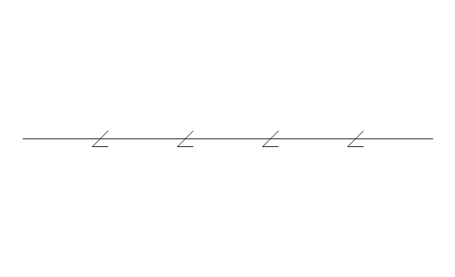
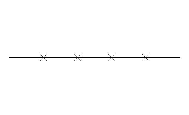
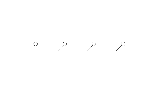
The vector stencils library "Transmission paths" contains 43 symbols of power transmission paths, electronic circuits, bus connectors and elbows, terminals, junctions, and concentrators.
Use it to annotate electrical diagrams, electronic schematics and circuit diagrams in the ConceptDraw PRO diagramming and vector drawing software extended with the Electrical Engineering solution from the Engineering area of ConceptDraw Solution Park.
www.conceptdraw.com/ solution-park/ engineering-electrical
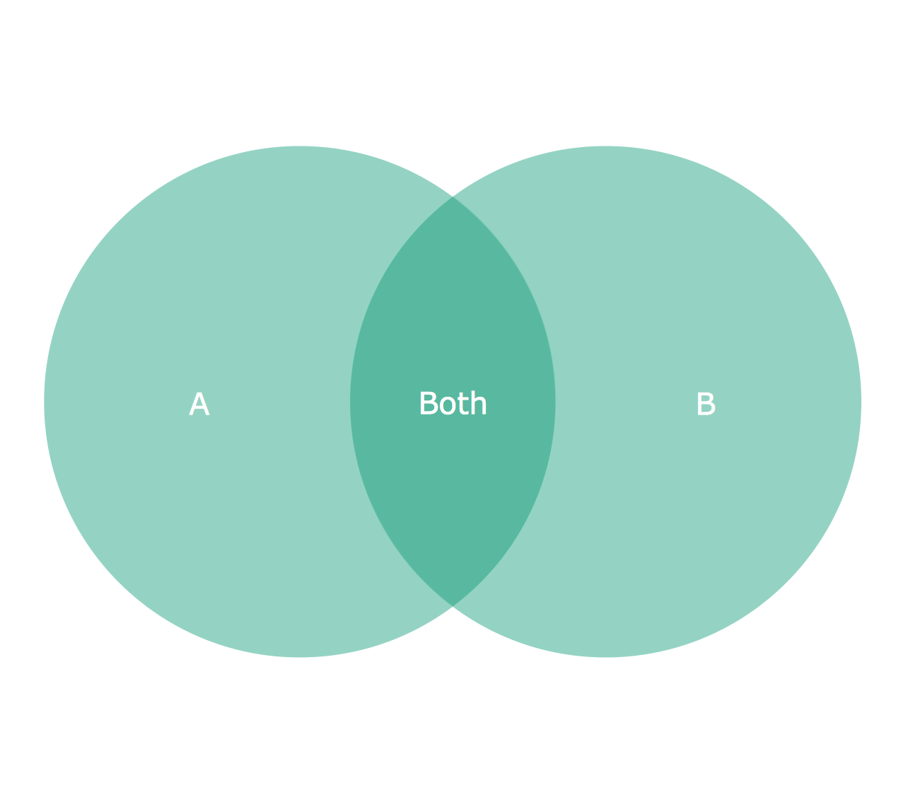
"A Venn diagram or set diagram is a diagram that shows all possible logical relations between a finite collection of sets. Venn diagrams were conceived around 1880 by John Venn. They are used to teach elementary set theory, as well as illustrate simple set relationships in probability, logic, statistics, linguistics and computer science." [Venn diagram. Wikipedia]
This 2-set Venn diagram template for the ConceptDraw PRO diagramming and vector drawing software is included in the Venn Diagrams solution from the area "What is a Diagram" of ConceptDraw Solution Park.
This 2-set Venn diagram template for the ConceptDraw PRO diagramming and vector drawing software is included in the Venn Diagrams solution from the area "What is a Diagram" of ConceptDraw Solution Park.
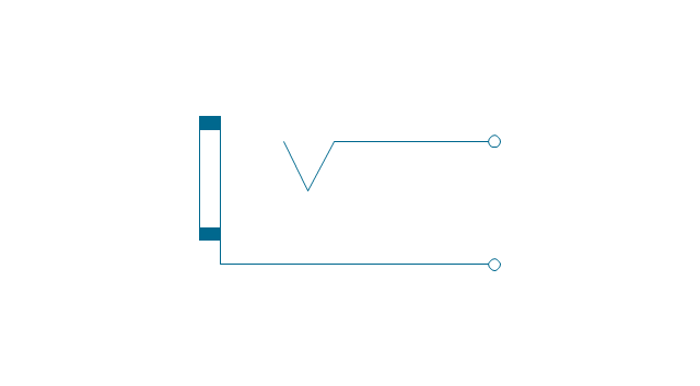
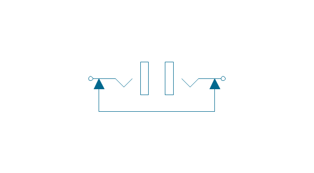
The vector stencils library "Terminals and connectors" contains 43 element symbols of terminals, connectors, plugs, polarized connectors, jacks, coaxial cables, and conductors.
Use it for drawing the wiring diagrams, electrical layouts, electronic schematics, and circuit diagrams in the ConceptDraw PRO diagramming and vector drawing software extended with the Electrical Engineering solution from the Engineering area of ConceptDraw Solution Park.
www.conceptdraw.com/ solution-park/ engineering-electrical
"In association football, the formation describes how the players in a team are positioned on the pitch. Different formations can be used depending on whether a team wishes to play more attacking or defensive football. ...
4–4–2.
This formation was the most common in football in the 1990s and early 2000s, so well known that it has even inspired a magazine title, FourFourTwo. The midfielders are required to work hard to support both the defence and the attack: typically one of the central midfielders is expected to go upfield as often as possible to support the forward pair, while the other will play a "holding role", shielding the defence; the two wide midfield players must move up the flanks to the goal line in attacks and yet also protect the fullback wide defenders." [Formation (association football). Wikipedia]
The diagram example "Association football (soccer) formation 4-4-2" was created using the ConceptDraw PRO diagramming and vector drawing software extended with the Football solution from the Sport area of ConceptDraw Solution Park.
www.conceptdraw.com/ solution-park/ sport-soccer
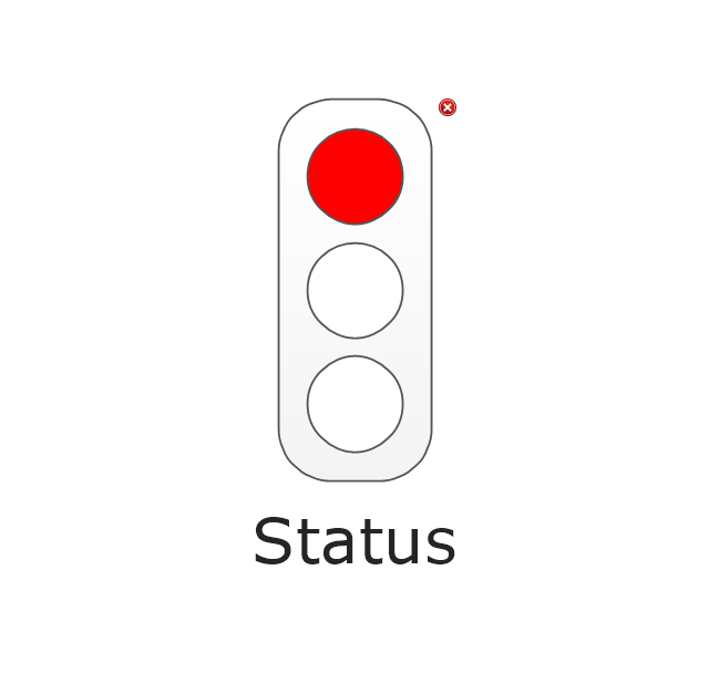
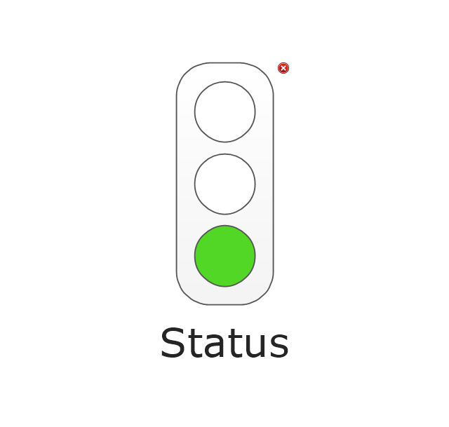
The vector stencils library "Status indicators" contains 41 visual status indicators. Each status indicator can visualize one of 2-6 information states and have a caption.
Use it to create your business performance dashboards in the ConceptDraw PRO diagramming and vector drawing software extended with the Status Dashboard solution from the area "What is a Dashboard" of ConceptDraw Solution Park.
Use it to create your business performance dashboards in the ConceptDraw PRO diagramming and vector drawing software extended with the Status Dashboard solution from the area "What is a Dashboard" of ConceptDraw Solution Park.
HelpDesk
How to Connect Tabular Data (CSV) to a Graphic Indicator on Your Live Dashboard
The Time Series Dashboard Solution can be used to create the interactive Time Series Charts as Column Charts, Line Charts, or Bar Charts for your interactive dashboard.- UML 2 4 Process Flow Diagram | Diagramming Software for Design ...
- Meter indicators 2 - Vector stencils library
- Venn diagrams - Vector stencils library | 2 Circle Venn Diagram ...
- 2 Circle Venn Diagrams
- 3-Tier Auto-scalable Web Application Architecture | 2 -Tier Auto ...
- Design elements - Swimlanes BPMN1. 2 | Design elements ...
- Design elements - Connections BPMN1. 2 | Design elements ...
- 2 -bit ALU - Logic gate diagram | Analog and digital logic - Vector ...
- Interior Design Piping Plan - Design Elements | Design elements ...
- 2 -Level 3D pyramid diagram - Template
- Association football (soccer) formation 2 –3–5 (pyramid) | Soccer ...
- Association football (soccer) formation 3- 2 -5 (WM) | Soccer (Football ...
- 2 -bit ALU - Logic gate diagram | Electrical Engineering | Electrical ...
- Venn Diagram Maker 2 Circles
- 2 Circle Venn Diagram Template
- Design elements - Connections BPMN1. 2
- Design elements - Swimlanes BPMN1. 2
- UML 2 4 Process Flow Diagram | Timing diagram | How to create a ...
- Soccer (Football) Formation | Association football (soccer) formation ...


-formation-diagram-association-football-(soccer)-formation-3-2-5-(wm).png--diagram-flowchart-example.png)
-formation-diagram-association-football-(soccer)-formation-2–3–5-(pyramid).png--diagram-flowchart-example.png)







,-1-valve-fluid-power-valves---vector-stencils-library.png--diagram-flowchart-example.png)
,-both-valves-fluid-power-valves---vector-stencils-library.png--diagram-flowchart-example.png)
,-no-valves-fluid-power-valves---vector-stencils-library.png--diagram-flowchart-example.png)
,-1-valve,-encl.-fluid-power-valves---vector-stencils-library.png--diagram-flowchart-example.png)
,-both-valves,-encl.-fluid-power-valves---vector-stencils-library.png--diagram-flowchart-example.png)
,-no-valves,-encl.-fluid-power-valves---vector-stencils-library.png--diagram-flowchart-example.png)
,-1-valve-fluid-power-valves---vector-stencils-library.png--diagram-flowchart-example.png)
,-both-valves-fluid-power-valves---vector-stencils-library.png--diagram-flowchart-example.png)
,-no-valves-fluid-power-valves---vector-stencils-library.png--diagram-flowchart-example.png)
,-1-valve,-encl.-fluid-power-valves---vector-stencils-library.png--diagram-flowchart-example.png)
,-both-valves,-encl.-fluid-power-valves---vector-stencils-library.png--diagram-flowchart-example.png)
,-no-valves,-encl.-fluid-power-valves---vector-stencils-library.png--diagram-flowchart-example.png)

-fluid-power-valves---vector-stencils-library.png--diagram-flowchart-example.png)
.png--diagram-flowchart-example.png)

















































-formation-diagram-association-football-(soccer)-formation-4-4-2.png--diagram-flowchart-example.png)


