HelpDesk
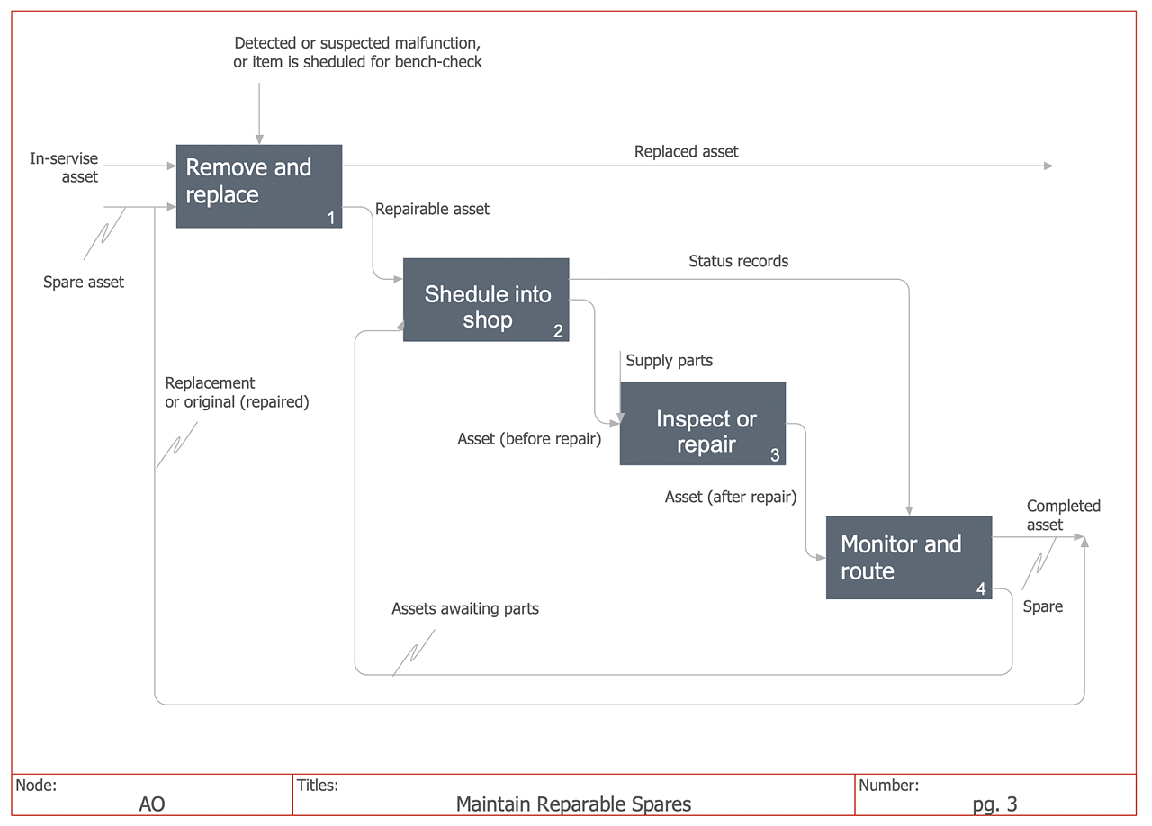
How to Create an IDEF0 Diagram for an Application Development
IDEF0 methods are intended to model the functions of a process, creating a graphical model that displays: what controls the function, who makes it, what resources are used and how they are connected with other functions. The IDEF0 tool is used to model the decisions, actions, and activities of a software system during the development process. IDEF0 diagram graphically depicts a model of a desired version of the application. ConceptDraw DIAGRAM allows you to create and communicate the IDEF0 diagrams of any complexity.UML Diagram
The accepted open standard that is used in software engineering and system design, when modeling object-oriented systems and business processes is known as Unified Modeling Language (UML). UML was created for definition, visualization, design and documentation software systems. It isn't a programming language, but on the base of UML model can be generated code. UML uses generic set of graphic notations for creation an abstract model of the system called UML-model. The UML notation lets visually represent requirements, subsystems, structural and behavioral patterns, logical and physical elements, etc. UML defines 13 types of diagrams: Class (Package), Use Case, Sequence, Object, Collaboration, Component, Timing, Interaction Overview, State Machine, Composite Structure, Activity, and Deployment. All these types of UML Diagrams can be fast and easy created with powerful ConceptDraw DIAGRAM software extended with special Rapid UML solution from Software Development area of ConceptDraw Solution Park.
 ConceptDraw Solution Park
ConceptDraw Solution Park collects graphic extensions, examples and learning materials
SSADM Diagram
The vector stencils library SSADM from the solution Systems engineering contains specific symbols of SSADM diagrams for ConceptDraw DIAGRAM diagramming and vector drawing software. The Systems engineering solution is contained in Software Development area of ConceptDraw Solution Park. The example below illustrates the waterfall model used in SSADM. This model involves 5 stages of developing a product such as requirements specification and its' analysis, design, coding and testing.
 Entity-Relationship Diagram (ERD)
Entity-Relationship Diagram (ERD) solution extends ConceptDraw DIAGRAM software with templates, samples and libraries of vector stencils from drawing the ER-diagrams by Chen's and crow’s foot notations.
- Diagram Visio Agile Process
- How to Create an IDEF0 Diagram for an Application Development ...
- PM Agile | Program Evaluation and Review Technique (PERT) with ...
- How to Create an IDEF0 Diagram for an Application Development ...
- PM Agile | How to Create an IDEF0 Diagram for an Application ...
- Agile Org Chart Examples
- PM Agile | Project Management Area | Quality Mind Map | Agile ...
- Anyone Have an ERD Symbols Quick Reference? | AWS ...
- PM Agile | SSADM Diagram | Organizational Charts with ...
- Conceptdraw.com: Mind Map Software, Drawing Tools | Project ...
- Program Evaluation and Review Technique (PERT) with ...
- PM Agile | Workflow diagram - Weather forecast | Velocity Chart
- Program Evaluation and Review Technique (PERT) with ...
- Flowchart Symbols Accounting. Activity-based costing (ABC ...
- Product life cycle process - Flowchart
- UML Sequence Diagram | UML package diagram - Template | UML ...
- Management | Management Area | Marketing | Holding Company ...
- Basic CCTV System Diagram. CCTV Network Diagram Example ...
- Functional Modeling Of Software Process Using Idef0
- Entity Relationship Diagram Software Engineering | Entity ...


