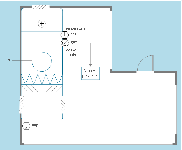
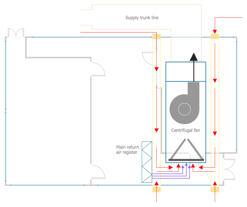
This HVAC floor plan sample illustrates the temperature sensors of air handler digital thermostat control.
"A thermostat is a component of a control system which senses the temperature of a system so that the system's temperature is maintained near a desired setpoint. The thermostat does this by switching heating or cooling devices on or off, or regulating the flow of a heat transfer fluid as needed, to maintain the correct temperature. The name is derived from the Greek words thermos "hot" and statos "a standing".
A thermostat may be a control unit for a heating or cooling system or a component part of a heater or air conditioner. Thermostats can be constructed in many ways and may use a variety of sensors to measure the temperature. The output of the sensor then controls the heating or cooling apparatus. A thermostat may switch on and off at temperatures either side of the setpoint the extent of the difference is known as hysteresis and prevents too frequent switching of the controlled equipment." [Thermostat. Wikipedia]
The HVAC plan example "Digital unit ventilator control" was created using the ConceptDraw DIAGRAM diagramming and vector drawing software extended with the HVAC Plans solution from the Building Plans area of ConceptDraw Solution Park.
Interior Design. Registers, Drills and Diffusers — Design Elements
The interior design project for any home, flat, business center includes the set of different plans and documents, among them obligatory are the ceiling plans. For creation these plans will be convenient to use professional drawing software. It is especially useful in cases when you need create and propose for customer the multiple alternative design plans for choice. ConceptDraw DIAGRAM diagramming and vector drawing software extended with Reflected Ceiling Plan solution is the choice of architects, designers, electricians, and other building-related people. It is ideal for displaying the ceiling design ideas which meet any requirements of building and budget. Included templates, samples and especially wide selection of vector design elements, including the elements offered by Registers, Drills and Diffusers library are helpful in drawing without efforts professional-looking Reflected Ceiling plans, Reflective Ceiling plans, Lighting Plans, Electrical Plans, Plans of location the outlets, grilles, diffusers, registers, light fixtures, light panels, etc.HVAC Business Plan
Long time you have looked for the convenient and helpful software for drawing HVAC Business Plan? Now ConceptDraw DIAGRAM diagramming and vector drawing software offers you the HVAC Plans Solution from the Building Plans Area that will help you create any desired HVAC Business Plan.- Air Conditioner Symbol Floor Plan
- HVAC Plans
- Airconditioning Floor Plan
- Ventilation system layout | HVAC Plans | How to Create a HVAC ...
- HVAC Plans | How to Create a HVAC Plan | Block diagram ...
- Typical Air Conditioning Architectural Layout Plan
- Design elements - HVAC ductwork | Ductwork layout | HVAC Plans ...
- HVAC Plans | How to Create a HVAC Plan | HVAC Marketing Plan ...
- Ductwork layout | Design elements - HVAC ductwork | Air handler ...
- Heat Vent Symbol For Floor Plan
- Heat Ventilation And Air Conditioning System
- Package Air Conditioner Symbol In Floor Plan
- Aircon Plan Symbols
- HVAC Marketing Plan | Design elements - HVAC control equipment ...
- Mechanical Drawing Symbols | How to Create a HVAC Plan | HVAC ...
- Design elements - HVAC control equipment | Building Drawing ...
- Hvac Floor Plans
- Ductwork layout | Ventilation duct system | Ventilation duct system ...
- Ductwork layout | HVAC Plans | Design elements - HVAC ductwork ...
- Design elements - HVAC equipment | Mechanical Drawing Symbols ...


