Circuits and Logic Diagram Software

Cisco Optical. Cisco icons, shapes, stencils and symbols

Electrical Drawing Software and Electrical Symbols

Electrical Symbols, Electrical Diagram Symbols

Wiring Diagrams with ConceptDraw DIAGRAM

Electrical Diagram

 Electrical Engineering
This solution extends ConceptDraw DIAGRAM.9.5 (or later) with electrical engineering samples, electrical schematic symbols, electrical diagram symbols, templates and libraries of design elements, to help you design electrical schematics, digital and analog
Fitness Plans
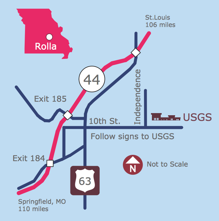
Maps and Directions
HelpDesk
How to Create a Fault Tree Analysis Diagram (FTD)

Total Quality Management Definition

How To Create CCTV Network Diagram

 Engineering
This solution extends ConceptDraw DIAGRAM.4 with the ability to visualize industrial systems in electronics, electrical, chemical, process, and mechanical engineering.
Electrical Symbols — Composite Assemblies

Mechanical Drawing Software

- Logical network topology diagram | Electrical Symbols — Logic Gate ...
- Logical network topology diagram | Circuits and Logic Diagram ...
- Diagram Of Computer Network Logic Gate
- 2-bit ALU - Logic gate diagram | How to Draw a Computer Network ...
- Diagrams Of Input Devices
- Logical network topology diagram | Network Diagram Software ...
- How to Draw a Computer Network Diagrams | How The Ven ...
- Circuits and Logic Diagram Software | Electrical Symbols — Logic ...
- Logic gate diagram - Template | Venn Diagram Template for Word ...
- Network Diagram Software Logical Network Diagram
- Electrical Symbols — Logic Gate Diagram | Electrical Symbols ...
- 2-bit ALU - Logic gate diagram | Initiation and annunciation - Vector ...
- Logical network topology diagram | Local area network (LAN ...
- Electrical Symbols — Logic Gate Diagram | Electrical Symbols ...
- Logical Network Diagram Vs Physical Network Diagram
- Logical network topology diagram
- Example Of Logic Circuit Diagram In Four Element
- Design elements - Logic gate diagram | Electrical Symbols ...
- Circuits and Logic Diagram Software | Venn Diagram Examples for ...
- Design elements - Logic gate diagram | Electrical Symbols ...